Wiring and Setting Up the System Excel 800
EN1B-0375GE51 R0910
28
Setting Address of Panel Bus I/O Modules
During CARE engineering, each Panel Bus I/O module is
assigned its own unique address. For the sake of clarity for
maintenance personnel, it is recommended that you
address the Panel Bus I/O modules in ascending order
0 through F.
Hex switch
0 1 2 3 4 5 6 7
Address
01 02 03 04 05 06 07 08
Hex switch
8 9 A B C D E F
Address
09 10 11 12 13 14 15 16
Table 24 HEX switch settings and addresses
► Use the rotary HEX switch to set the address to the one
already defined during CARE engineering.
LOCK
4
4
Fig. 38 HEX switch location
Notes
If the HEX switch is changed, the Panel Bus I/O module
will revert to its default configuration.
With LONWORKS Bus I/O modules, the HEX switch is
without function.
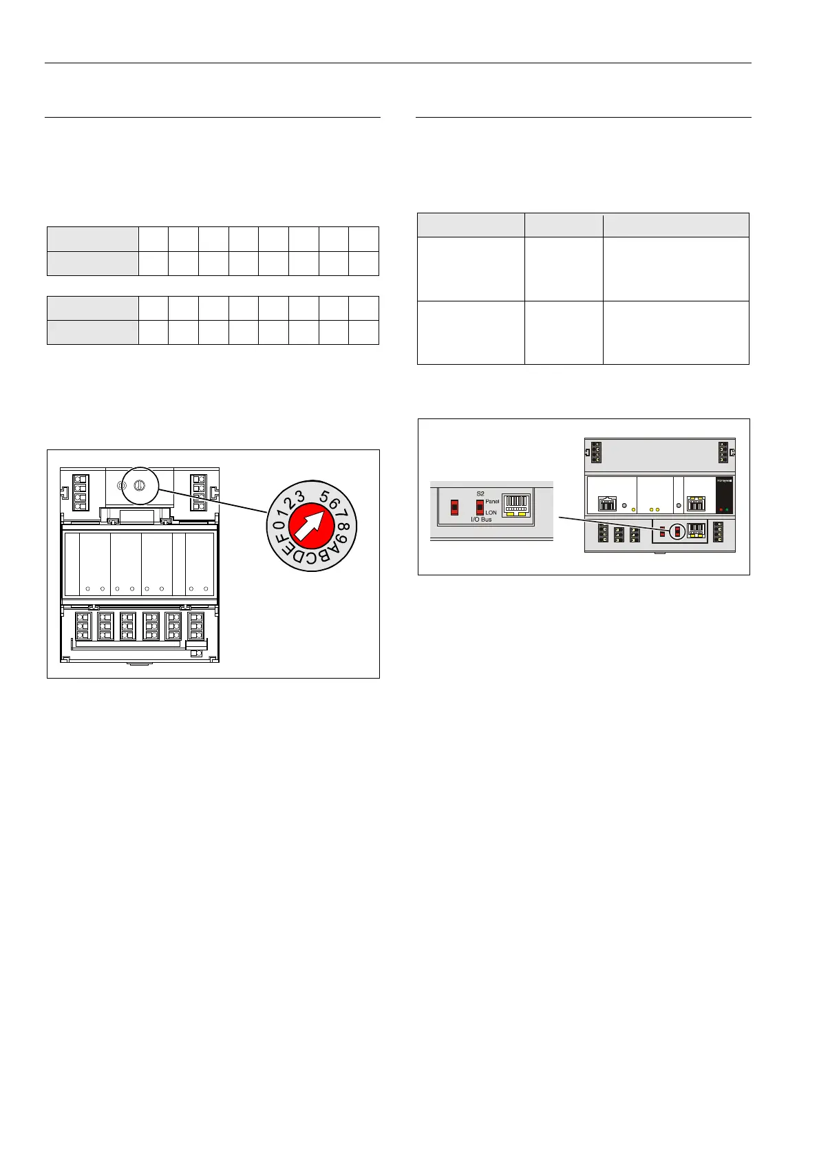
Setting I/O Bus Switch
► Set the I/O Bus switch S2 of the XCL8010 Controller
Module depending on the modules connected to
terminals 71 … 78 and the desired communication as
follows:
Communication S2 setting Terminals
LONWORKS Bus
only
LON 71 … 74 L
ONWORKS Bus
75 … 78
LONWORKS Bus
11 … 14
LONWORKS Bus
Panel Bus and
L
ONWORKS Bus
Panel 71 … 74 Panel Bus
75 … 78 Panel Bus
11 … 14 L
ONWORKS Bus
Table 25 I/O Bus switch settings
Fig. 39 S2 I/O Bus switch
 Loading...