Description of the XCL8010 Controller Module Excel 800
EN1B-0375GE51 R0910
34
XCL8010 Terminals
74
78
73 77
72
76
71
75
COM
B
COM
B
COM
A
COM
A
1
2
3
4
13
14
8
5
C+ C+
C- C-9 6
10 7
SHIELD SHIELD
11
12
LON
1
LON
1
LON
2
LON
2
NC
8 7 6
5
4 3 2 1
*WATCHDOG
RELAY
*
24
V
~
24
V
~
24
V
~
24
V
~
0
24
V
~
0
24
V
~
0
24
V
~
0
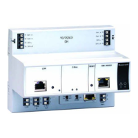
Fig. 49 Terminal assignment and internal connections of
the XCL8010
Controller Module
Ter-
minal
Signal Comment
71, 75 COM a
2-wire communication bus
(LON/Panel Bus)
72, 76 COM b
2-wire communication bus
(LON/Panel Bus)
73, 77 24 V~ Power supply for I/O modules
74, 78 24 V~0 Power supply for I/O modules
1 24 V~ Power supply from transformer
2 24 V~0 Power supply from transformer
3 24 V~0 Alarm/watchdog output
4 NC Alarm/watchdog output
5, 8 C+ C-Bus
6, 9 C- C-Bus
7, 10 Shield C-Bus shield
11, 12 LON LONWORKS IN
13, 14 LON LONWORKS OUT
Table 28 Description of XCL8010 terminals
Features
LONWORKS Interface and Terminals
The XCL8010 Controller Module features
An RJ45 socket serving as an interface
to connect laptops to the L
ONWORKS Bus
LONWORKS terminals 11, 12, 13, and 14
to connect L
ONWORKS Bus I/O modules or other
L
ONWORKS devices to the XCL8010 Controller or other
L
ONWORKS controllers.
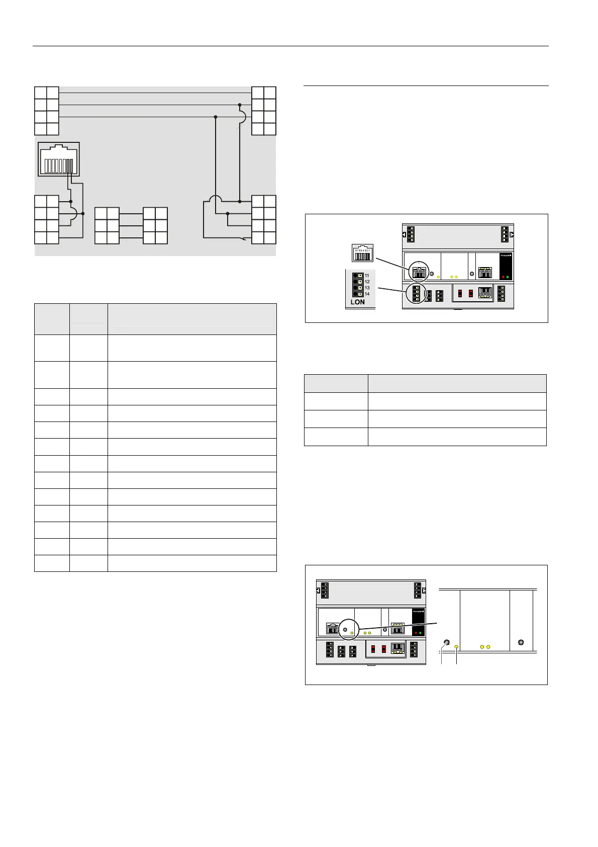
Fig. 50 LONWORKS interface and LONWORKS terminals
LONWORKS Interface Signals on RJ45 Socket
Pin Signal type
1 Connection to LONWORKS Bus
2 Connection to LONWORKS Bus
3 … 8 Not used
Table 29 Signals of LONWORKS interface
LONWORKS Service LED and Button
The XCL8010 Controller Module is equipped with a
L
ONWORKS service button and corresponding LONWORKS
Service LED (status: yellow/OFF).
1
LON
2
Fig. 51 LONWORKS service button (1) and service LED (2)
See also section "Troubleshooting" on page 73.
 Loading...