Excel 800 Wiring and Setting Up the System
29 EN1B-0375GE51 R0910
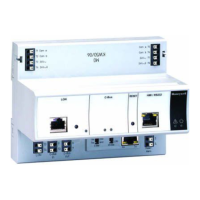
Connecting Field Devices
Connecting Field Devices with Power Supply
Depending on the distance from the controller, field devices
can be supplied by the controller or need a separate
transformer, see Table 20 on page 13.
For fusing see section "Fusing Specifications" on page 10.
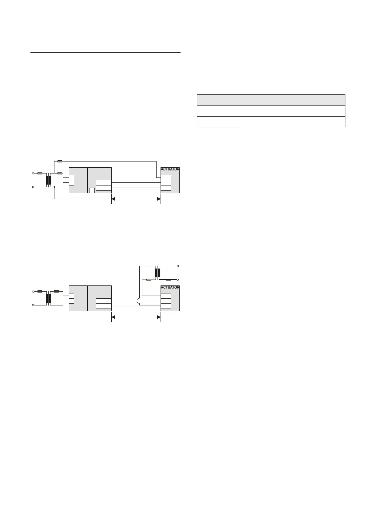
Example 1: Power Supply via Controller
24 V actuator connected to an analog output module
Less than 100 m away from the controller
Y (0...10 Vdc)
24 V0
230 V~
24 V~
max. 100 m
XCL8010
822
1
2
9
1...8
GND
24V
~
11...18
F1
F2
Fig. 40 Power supply of field devices via I/O module
Example 2: Power Supply via Separate Transformer
24 V actuator connected to an analog output module
100 … 400 m away from the controller
Y (0...10 Vdc)
24 V0
24 V0
230 V~
230 V~
24 V~
24 V~
max. 400 m
XCL8010
822
1
2
1...8
GND
24V
~
11...18
F1
F2
Fig. 41 Power supply of field devices via a separate
transformer
Cabling Field Devices
Cable Routing
Route low-voltage signal and output cables separately from
mains cables.
Cable Minimum distance
Shielded 10 mm (0.4 in.)
Unshielded 100 mm (4 in.)
Table 26 Minimum distances to power mains cables
All low-voltage signal and output cables should be regarded
as communication circuits in accordance with VDE 0100
and VDE 0800 (or NEC or other equivalent).
Cable Shielding
If the general guidelines for cable routing are observed, it
is not necessary to shield field device signal and power
supply cables.
If, for whatever reason, the routing guidelines cannot be
observed, the field device signal and power supply
cables must be shielded.
– Shielding of cables leading to field devices must be
grounded only at the cabinet end.
– The shield must not be terminated at the XCL8010
Controller Module.
 Loading...