EasyManua.ls Logo

Honeywell Excel 800 SYSTEM User Manual

Honeywell Excel 800 SYSTEM
92 pages
To Next Page IconTo Next Page
To Previous Page IconTo Previous Page
Page #30 background imageLoading...
Page #30 background image
Wiring and Setting Up the System Excel 800
EN1B-0375GE51 R0910
30
Commissioning I/O Modules
Commissioning Panel Bus I/O Modules
During CARE engineering, the HEX address of the Panel
I/O modules is defined.
Note
In the case of Panel Bus I/O modules, it is essential that the
HEX switch be set to the address assigned during CARE
engineering.
The XCL8010 Controller automatically commissions all
Panel Bus I/O modules.
Commissioning LONWORKS Bus I/O Modules
Commissioning is done using CARE.
Updating Software
The XCL8010 Controller’s software can be updated using
CARE.
Software with Panel Bus I/O Modules
The XCL8010 Controller’s firmware includes the firmware
for the Panel Bus I/O modules. Thus, whenever the
XCL8010 Controller’s firmware is updated, the firmware of
the Panel Bus I/O modules is automatically updated, too.
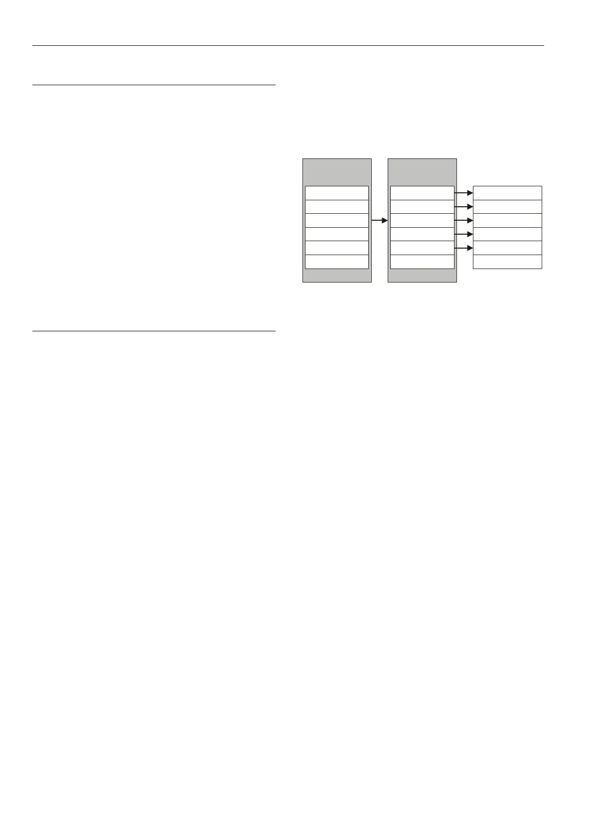
Example
Status before update: The XCL8010 Controller was loaded
with controller firmware V3.01.03, which included the cor-
responding Panel Bus I/O module firmware as shown in the
accompanying figure.
When the controller firmware is updated from V3.01.03 to
V3.02.02, if newer firmware is available for individual Panel
Bus I/O modules, their firmware will be automatically
updated, too. In this example, newer Panel Bus I/O module
firmware is, indeed, available for all but the XF830A Mixed
Panel Bus I/O modules. As a consequence, the firmware of
all of the Panel Bus I/O modules – except for the XF830A
Mixed Panel Bus I/O modules – will be updated,
accordingly.
XCL8010A
firmware V3.01.03
XCL8010A
firmware V3.02.02
XF821A firmware V1.01.01 XF821A firmware V1.01.05
XF821A updated to V1.01.05
XF822A firmware V1.01.01 XF822A firmware V1.01.05
XF822A updated to V1.01.05
XF823A firmware V1.01.00 XF823A firmware V1.01.04
XF823A updated to V1.01.04
XF824A firmware V1.01.00 XF824A firmware V1.01.04
XF824A updated to V1.01.04
XF825A firmware V1.01.00
XF830A firmware V1.00.02
XF825A firmware V1.00.02
XF825A updated to V1.00.02
XF830A firmware V1.00.02
XF830A not updated
Fig. 42. Automatic updating of Panel Bus I/O module
firmware (example)
Note
Panel Bus I/O modules feature a so-called watchdog
functionality. Consequently, if the firmware of the given
Panel Bus I/O module stops running (due, e.g., to updating),
this watchdog functionality will switch OFF the module’s
outputs (if present) – even if the corresponding manual
overrides (if present) have been set to ON. Thus, the
manual overrides should NOT be thought of as emergency
overrides; rather, they are subordinate to the given Panel
Bus I/O module’s processor and firmware.
Software with LONWORKS Bus I/O Modules
The software of the LONWORKS I/O modules can be updated
using CARE or EXCELON.

Table of Contents

Questions and Answers:

Honeywell Excel 800 SYSTEM Specifications

General IconGeneral
BrandHoneywell
ModelExcel 800 SYSTEM
CategoryController
LanguageEnglish

Summary

Safety Information

General Safety Information

General safety instructions for installation, operation, and handling of the Excel 800 System.

Safety Information as per EN60730-1

System data and safety requirements according to EN60730-1 standard.

System Overview

I/O Modules

Description of pluggable and mixed I/O modules, including color coding and terminal sockets.

Interfaces and Bus Connections

Details on Panel Bus, LONWORKS Bus, C-Bus, HMI, and Modem interfaces.

Planning

Transformer Selection

Guidelines for selecting appropriate transformers, considering power consumption and types.

Mounting/Dismounting Modules

Mounting/Dismounting Controller/Sockets

Instructions for mounting controllers, sockets, and determining maximum I/O module counts.

Mounting/Dismounting Electronic Modules

Procedures for inserting and removing electronic modules from sockets, including locking mechanisms.

Mounting/Dismounting Manual Disconnect Modules

Steps for mounting and dismounting manual disconnect modules, including safety warnings.

Mounting/Dismounting Auxiliary Terminal Packages

Instructions for mounting and dismounting auxiliary terminal packages for I/O modules.

Wiring and Setting Up the System

General Safety Considerations

Safety guidelines for electrical work, grounding, and handling electrostatic devices.

Wiring Terminals

Details on push-in and screw-type terminals, including wiring specifications.

Connecting Power Supply

Methods for connecting power supply, including single transformer and additional transformers.

Connecting to External Systems or Interfaces

Description of the I/O Modules

Analog Input Modules

Types, features, terminals, and technical data for analog input modules.

Analog Output Modules

Types, features, terminals, technical data, and status LED behavior for analog output modules.

Binary Input Modules

Types, features, terminals, technical data, and configuration for binary input modules.

Relay Output Modules

Types, features, terminals, permissible loads, and status LED behavior for relay output modules.

Floating Output Module

Features, permissible loads, status LED behavior, and override modes for floating output modules.

Mixed Panel Bus I/O Modules

Features, permissible loads, and terminal assignments for mixed Panel Bus I/O modules.

LON Software Interface Description

XFL821 Analog Input Module

LONMARK profile, input types, and network variables for XFL821.

XFL(R)822 Analog Output Module

LONMARK object, control levels, and network variables for analog output modules.

XFL823 Binary Input Module

LONMARK object, digital input types, and network variables for binary input modules.

XFL(R)824 Relay Output Module

LONMARK object and relay output command network variable.

Troubleshooting

Controller LED Troubleshooting

Using controller LEDs (Power, Alarm, LON, C-Bus, HMI, Modem) for troubleshooting.

I/O Module Troubleshooting

Common problems and remedies for I/O modules, including Power and Service LEDs.

Appendix 1: System Protective Earth Grounding

Appendix 2: Remote Communications

Related product manuals