Description of the XCL8010 Controller Module Excel 800
EN1B-0375GE51 R0910
36
Alarm and Power LEDs
The XCL8010 Controller Module is equipped with an alarm
LED and a power LED.
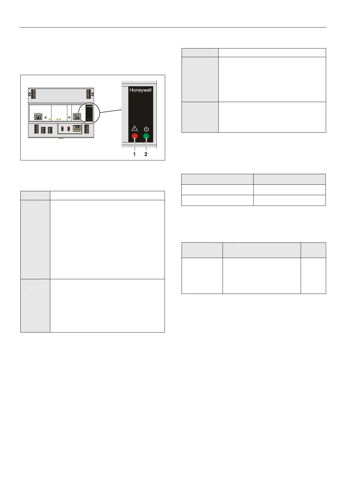
Fig. 55 Alarm LED (1) and power LED (2)
Alarm LED (1, red)
Off
Normal operation
On
Watchdog alarm output is powered
The controller has encountered a
hardware problem
The application has a fault
The controller has been powered up
without an application or the operator has
manually stopped the application,
e.g., using XL-Online.
In this case, the LED will light up
13 minutes after power-up without
application
Flashing The watchdog alarm output has not yet been
powered, although the controller has
encountered a problem.
The controller performs a warm start.
If problem persists, the LED will become lit
constantly, see above.
See section "Troubleshooting" on page 73.
Table 33 Controller alarm LED
Power LED (2, green)
On
Normal operation
Flashing One or more of the internal voltage
supplies are outside of the permissible
ranges.
The controller stops operation.
► Check wiring or see section
"Troubleshooting" on page 73.
Is ex-
tinguished
briefly
The operator has activated the reset
button
The controller is performing a warm
start
Table 34 Controller power LED
Watchdog
Watchdog Status
Status Signal on terminal 4
Failure (= alarm) 24 V
Normal operation 0 V
Table 35 Watchdog status 4
Permissible Load of Normally Closed Contact
(Terminal 4)
Max. load
Min.
current
Per normally
closed
contact
(terminal 4)
19…29 VAC
current at cos φ ≥ 0.95: 0.5 A,
current at cos φ ≥ 0.6: 0.5 A
19…29 VDC
0.5 A resistive or inductive
10 mA
Table 36 Permissible load of terminal 4
 Loading...