Description of the I/O Modules Excel 800
EN1B-0375GE51 R0910
62
Terminals
ANALOG
INPUTS
ANALOG
OUTPUTS
24 V RELAYSGND
BINARY
INPUTS
1
B1
2
B2
3
B3
4
B4
5
B5
6
B6
7
B7
8 9 10 11 12
B8 B9
B10 B11 B12
13
1414
15 16
AI1
AI2
AI2 AI3 AI4
17 18 19 20
AI5 AI6
AI7
AI8
25 26 27
21 22
23
24
28
AO5 AO6 AO7
AO1 AO2 AO3 AO4
AO8
41
G1
42
G2
74
73
72
71
24
V
~
24
V
~
0
COM
B
COM
A
78
77
76
75
24
V
~
24
V
~
0
COM
B
COM
A
J1 J2 J3 J4 J5
IN1
NO1
35
29
IN2
NO2
36
30
IN3
NO3
37
31
IN4
NO4
38
32
IN5
NO5
39
33
IN6
NO6
40
34
R1 R2
R3
R4
R5 R6
EXT. 24VAC FOR
RELAY COMMON
JUMPER JUMPER JUMPER JUMPER JUMPER
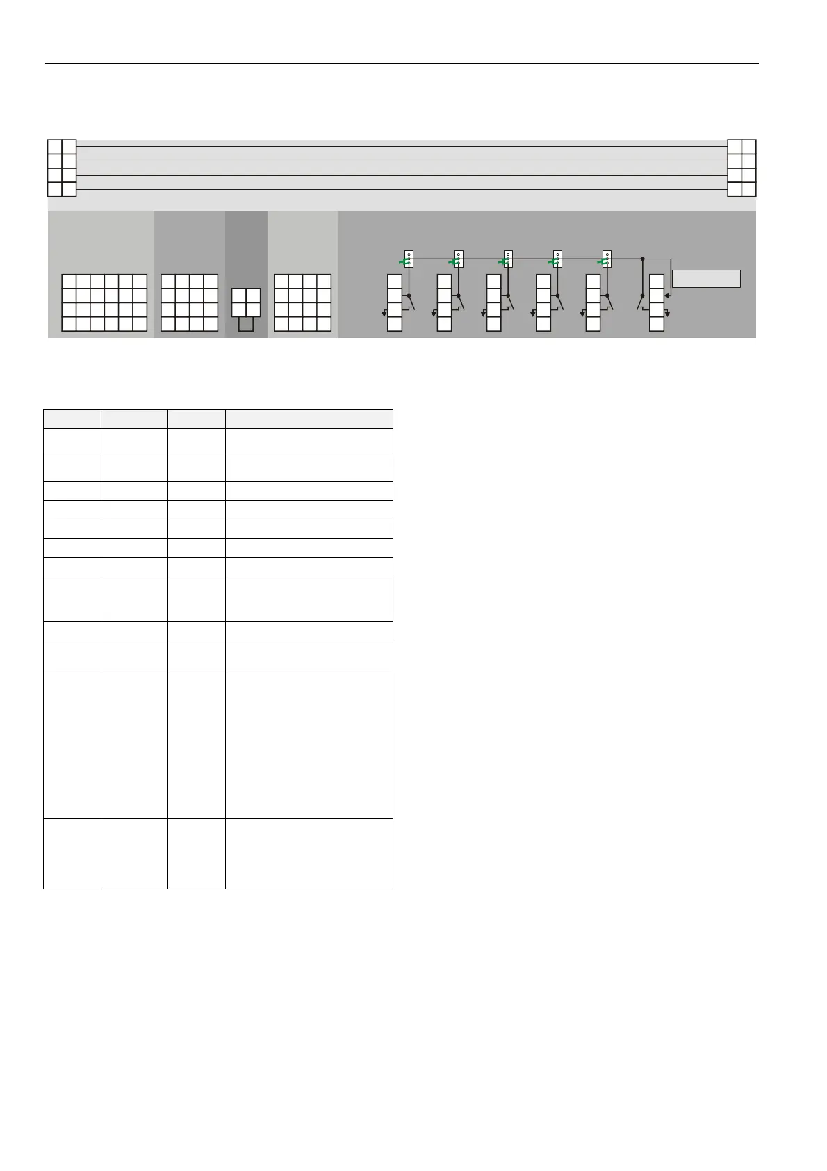
Fig. 88 Terminal assignment and internal connections of mixed Panel Bus I/O module terminals
Terminal Signal LED Comment
71, 75 COM a
status
2-wire communication bus
(Panel Bus)
72, 76 COM b
status
2-wire communication bus
(Panel Bus)
73, 77 24 V~ power Power supply
74, 78 24 V~0 power Power supply
1…7 BI1…7 1…7 Binary inputs 1…7
8…12 BI8…12 24…28 Binary inputs 8…12
13…20 AI1…8 -- Analog inputs 1…8
41, 42
GND
--
Ground. Both grounds are
internally connected to each
other and to 24 VAC0.
21…28 AO1…AO8 -- Analog outputs 1…8
29…34 NO1…6 29…34
Relays 1…6, normally-open
contacts
35…39 IN1…5 --
Common contacts of relays
1…5. May be set to common
supply voltage via terminal 40
by inserting jumpers J1…J5 into
their lower positions. When, in
contrast, a jumper is in the
upper position (the so-called
“parking position” = default
setting), the corresponding relay
receives no supply voltage from
terminal 40.
40 IN6 --
Common contact of relay 6,
internally connected to the
middle contact of jumpers
J1…J5. May be used to connect
common supply voltage.
Table 61 Description of mixed Panel Bus I/O module
terminals
 Loading...