Design and Implementation of HC900 Control System - HC900 Control System Operational Modes
46 HC900 Process & Safety Controller Safety Manual Revision 1.9
01/14
HC900 Control System Operational Modes
Refer installation guide information on operating modes.
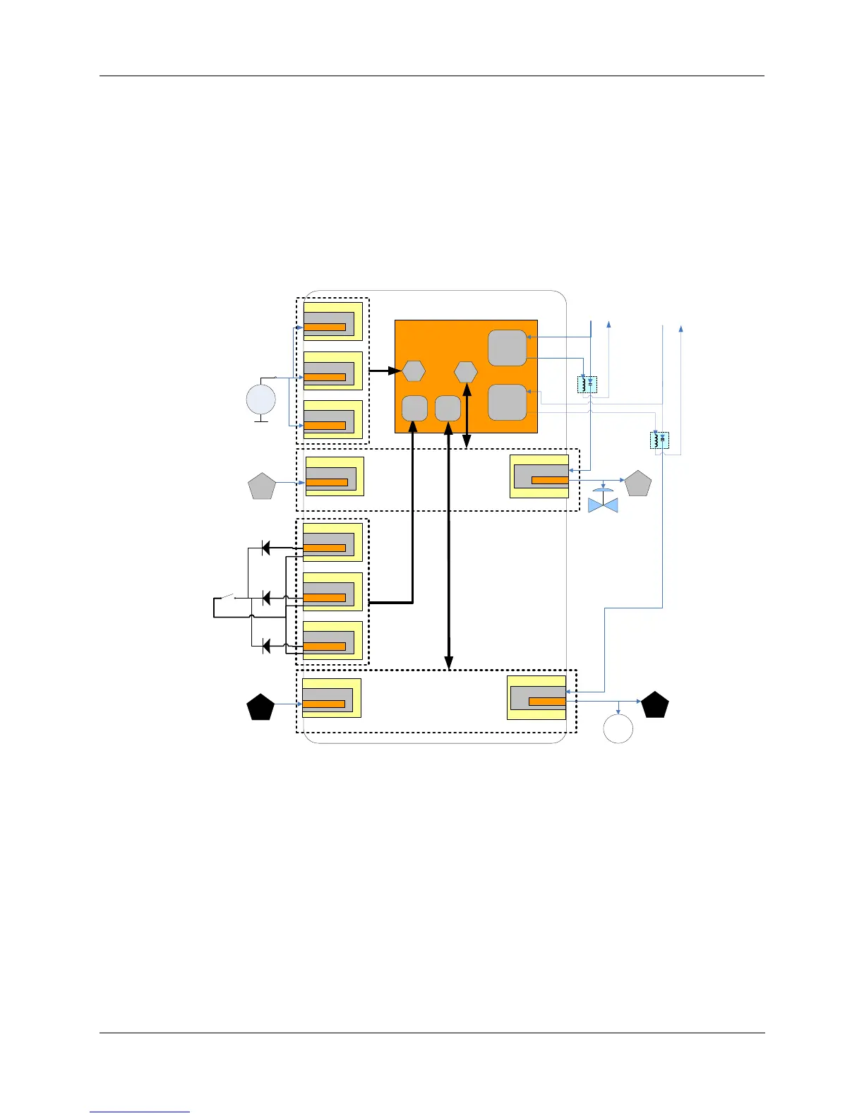
Hardware and wiring requirements for safety configuration
The IO channels used in a safety configuration require approved listed IO modules and interconnected to
ensure proper fault detection and action is achieved. The diagram below outlines this wiring concept.
xx
yyy
Rack ‘1’
AI Module
Channel ‘z'
Rack ‘2’
AI Module
Channel ‘z'
Rack ‘3’
AI Module
Channel ‘z'
Rack ‘1’
AO Module
Channel ‘z'
Rack ‘1’
AI Module
Channel ‘z'
Rack ‘1’
DI Module
Channel ‘z'
Rack ‘2’
DI Module
Channel ‘z'
Rack ‘3’
DI Module
Channel ‘z'
Rack ‘1’
DO Module
Channel ‘z'
Rack ‘1’
DI Module
Channel ‘z'
Users Safety Worksheet configuration
DI-V DO-V
M
*
*
*
Master
Field power
Digital N.O.
Contact
Field Power
AI-V
AO-V
Master
Field power
Digital N.O.
Contact
Field Power
A
A
B
B
External Master
Field Relay
* External diodes are
required on contact
inputs (900G01-xxxx)
External Master
Field Relay
Figure 12 – IO-V function block connections
The external master field relay shown in Figure 12 is further demonstrated in Figure 13 through Figure 15.
They demonstrate the connection of the series output relay’s NORMALLY OPEN contact to protect
against outputs that are stuck “ON”. This relay may be added individually as shown in Figure 13 and
Figure 15 or common for multiple channel outputs as shown in Figure 14 and Figure 15. The external
master field relay must be configured to open when the DO-V or AO-V functions on the safety worksheet
indicate a failure with the Fail or VFail pin “ON”.

 Loading...


