Design and Implementation of HC900 Control System - HC900 Safety configurations
50 HC900 Process & Safety Controller Safety Manual Revision 1.9
01/14
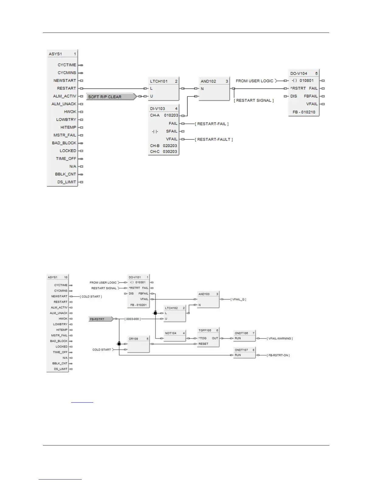
Figure 17 – Sample controlled start-up configuration
Module Replacement
DO-V and AO-V use an input module to verify the output’s value. Failure of the input module will cause the
FBFAIL pin the “ON” state; however the output of the block unless configured otherwise with logic will maintain
the output value without verification. Caution: configuration considerations must be taken by the user
configuration to prevent a verify fail and resulting failsafe action when repairing the failed input module.
Figure 18 – Sample VFAIL qualification
Figure18 illustrates a means to prevent VFAIL from turning on immediately after the input module is
replaced. FBFAIL driving high is latched by LTCH102 which when ANDed with an inverted input to
AND103 prevents the qualified VFAIL signal, VFAIL_Q, from driving ON. This configuration
enhancement allows the user to replace the failed input module without causing a VFAIL trip since the
module will be restarted automatically prior to reconnecting the field connections. The user would
subsequently re-enable VFAIL when it is LOW by toggling FB-RSTRT ON then OFF thus clearing the

 Loading...


