Mounting and installation
12
Connecting the thermal actuators
Damage to the underoor
heating controller.
Take the technical data into account at
thermal actuators:
Total of 3A maximum current, 250mA
continuous current per zone.
!
Each zone can control up to 3 thermal actuators. 3
thermal actuators can be connected directly for Zone
1, 2 for Zone 2 and 1 thermal actuator each for Zones
3 through 5. One connection for the expansion module
is available for each of the zones 6 through 8.
If more than 11 thermal actuators are to be connected to
the underfloor heating controller, the cables of the thermal
actuators must be connected in a distribution box.
If applicable, install the cables of the thermal
actuators to the distribution box.
Wire the wires of the thermal actuators.
Break out the openings for the cables on
the housing using a diagonal cutter.
Strip the connections 5.5 mm (see
fold-out page, Fig. 6).
Insert the connecting cables of the thermal actuators
into the cable openings of the connectors.
Close the terminals.
Plug the connectors into the sockets
of the corresponding zones (see fold-
out page, Fig. 4 (Z1...Z8)).
8
Clamp the cables into the stress relief clamp.
Secure the cable with the cable clamp.
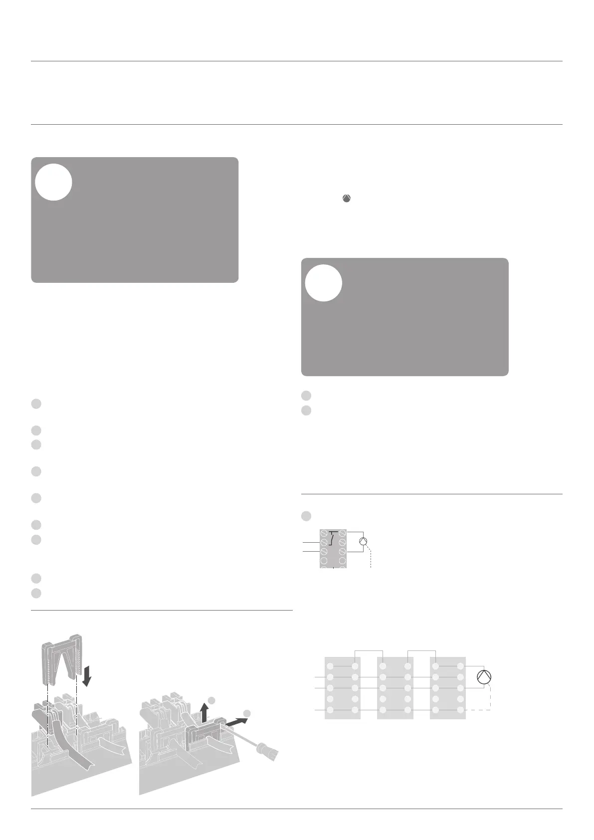
Connecting a pump
(
230 V AC
)
As soon as a zone is active, the pump is
activated with a time delay. The pump switches
off as soon as all the valves are closed.
The LED (see fold-out page, Fig. 3 (6)) lights
up green when the pump is running.
The pump contact is not floating. The pump can
be connected directly, see circuit diagram.
Damage to the underoor
heating controller.
Short-circuit at incorrect installation.
Connect all the controllers
to the same phase.
!
Strip the connections 7 mm (see fold-out page, Fig. 7).
Connect the pump (see fold-out page, Fig.4 (12)).
Installation Disassembling
1
2
Cabling –
continued
L
N
PE
N
Pum
p
Controller 2 Controller 3
Pump connection
Pum
PE
 Loading...