Section 2: Mounting and Wiring
11
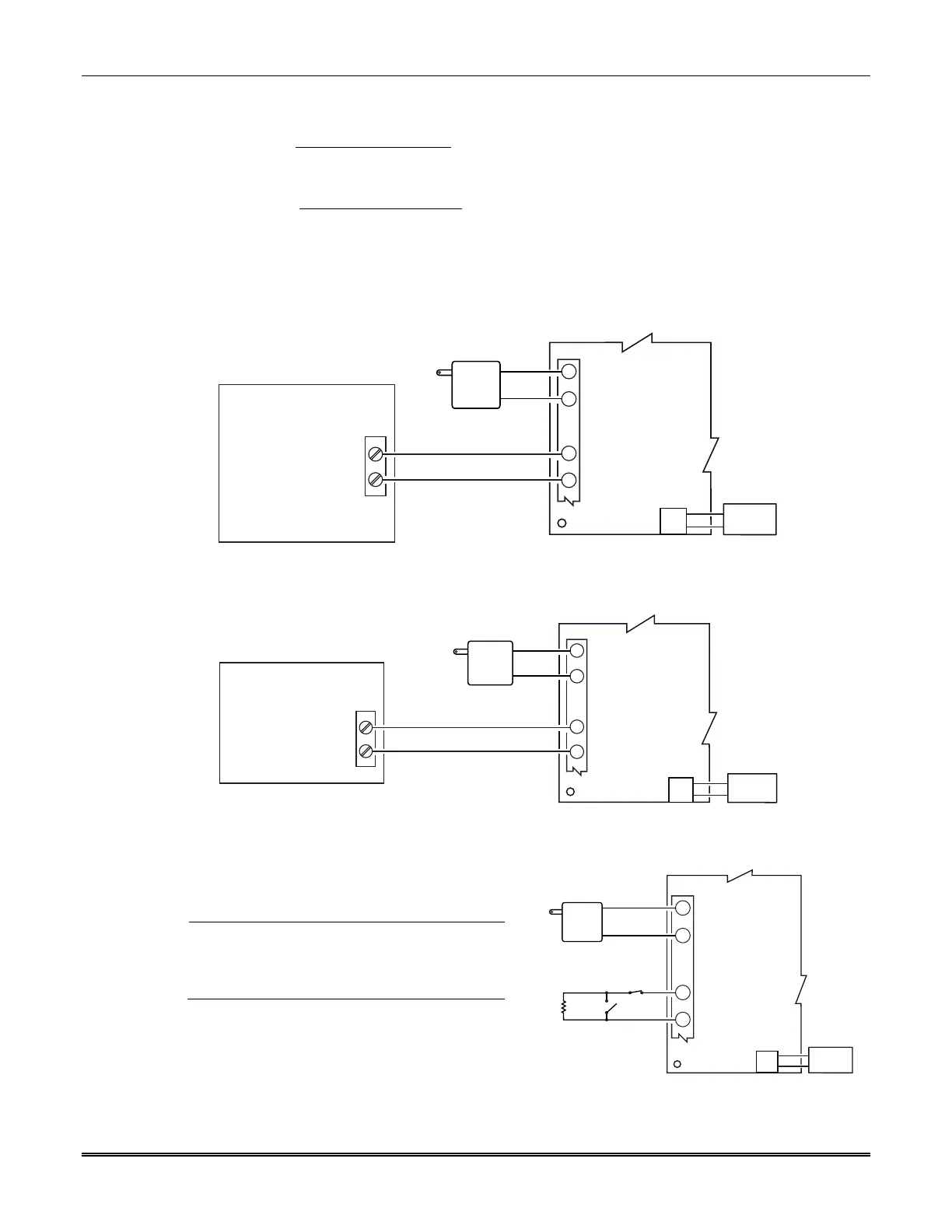
Wiring for Zone Trigger Mode
To trip a zone using a positive trigger, the voltage level must be:
6V or greater = positive trigger. (Levels above +14V may cause damage to the unit.)
4V or less = restore.
To trip a zone using a negative trigger, the voltage level must be:
4V or less = negative trigger.
6V or greater = restore. (Levels above +14V may cause damage to the unit.)
Note: Remember to program the communicator zone for the desired trigger type.
Connect a wire from the triggering source (bell output, voltage trigger, etc.) of the control panel to
the zone input of the communicator, and connect a common ground between the communicator
and control panel. Examples of zone connections follow:
COMMUNICATIONS
MODULE
TRIGGERING DEVICE
GSMV-005-V0
GND
GND
ZONE INPUT Z1/Z2
2
1
4
5
TB1
TRANSFORMER
AC INPUT 2
AC INPUT 1
+ TRIGGER
(VOLTAGE: 6 to 13V)
J1
BATTERY
Wiring the Zone 1 Input for a Positive (+) Trigger
TRIGGERING DEVICE
GSMV-006-V0
GND
GND
ZONE INPUT Z1/Z2
2
1
4
5
TB1
TRANSFORMER
AC INPUT 2
AC INPUT 1
-
TRIGGER
(VOLTAGE 4 to 0V)
COMMUNICATIONS
MODULE
J1
BATTERY
Wiring the Zone 1 Input for a Ground (-V) Trigger
iGSMBR-010-V0
GND
ZONE INPUT Z1/Z2
2
1
4
5
TB1
TRANSFORMER
AC
AC
2K EOL
RESISTOR
N.C.
N.O.
COMMUNICATIONS
MODULE
J1
BATTERY
Wiring the Zone 1 Input for EOL Supervised N.O./N.C. Triggers
UL/ULC
Zones should use EOL resistors, and be pro-
grammed as V+ Inverted or V– Inverted opera-
tion such that a cut line results in an alarm.
Do not use zones 1 and 2 for UL installations.
 Loading...