LTE-I Installation and Setup Guide
14
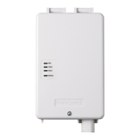
COMMUNICATION MODULE
CONTROL PANEL
comm_mod-001-V1
GND
ECP DATA OUT
ECP DATA IN
ECP (+) VOLTAGE INPUT
GND
DATA I N
BLK
YEL
GRN
RED
DATA OUT
+12 V AUX
2
6
1
4
5
3
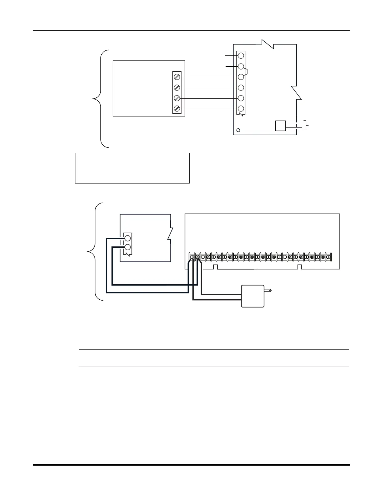
TB1
NO CONNECTION
J1
AC INPUT 2
AC INPUT 1
NO CONNECTION
NO CONNECTION
NOTE: DO NOT CONNECT THE COMMUNICATION
MODULE BACKUP BATTERY OR TRANSFORMER
FOR COMMERCIAL FIRE & BURGLARY INSTALLATIONS.
ULC: For ULC Commercial
Burglary Zone Trigger
installation see above
referenced "Zone Trigger Setup"
CONTROL PANEL
TO 110 VAC
UNSWITCHED
OUTLET
iGSMBR-014-V1
12
30 FT. MAX TO MODULE
18 AWG. WIRE (MIN)
HONEYWELL 1361 OR 1361-GT
TRANSFORMER
2
1
COMMUNICATIONS
MODULE
NOTE: Shared Transformer Installation has not been evaluated by UL/ULC.
NOTE: When calculating the total load on the auxiliary power output of the control panel, budget 10mA
for the communicator when using ECP mode.
ULC Commercial
Fire and Burglary
Compliant
Installation
Shared
Transformer
Installation

 Loading...