PAGE - 8 Installation Manual AM-1000
NOTIFIER ITALIA Doc. M-145.1-AM1000-ENG Rev A.2 AM1000_manu
C
C
I
I
R
R
C
C
U
U
I
I
T
T
W
W
I
I
T
T
H
H
L
L
O
O
O
O
P
P
(
(
S
S
T
T
Y
Y
L
L
E
E
6
6
)
)
C
C
O
O
N
N
N
N
E
E
C
C
T
T
I
I
O
O
N
N
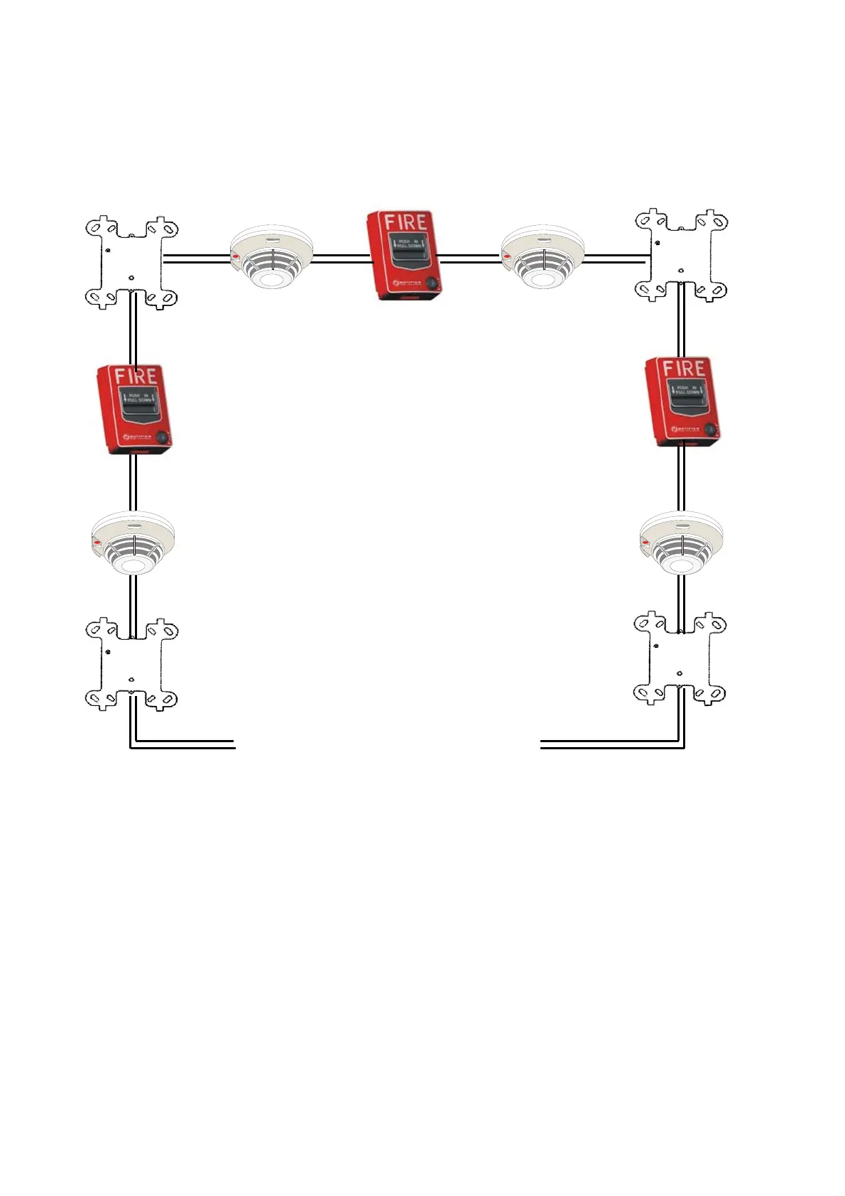
The functions are in accordance with the technical details regarding the signalization circuits NFPA STYLE 6
%
NOTE: The maximum number of devices between two ISO-X is 25.
WORKING
To protect each device against the opening and the short-circuit (of all the other section) it is necessary to
separate each group of devices, connected on the SLC line, with a couple of ISO-X isolator of trouble
module.
For example, a trouble on the section 2 will not influence the sections 1 and 3.
The isolator module on both ends of the section 2 will cause the opening of the SLC line.
The section 1 will continue to operate by the supply from the canal “A”, the section 3 will continue through
the canal “B”.
Since the control panel will not be able to communicate with the devices of the SLC line of section 2, it will
be generate a trouble signalization (ANSWEAR NOT VALID from the Points of the section 2).
The circuit is a variation of the circuit regarding the STYLE 6 NFPA signalization line, so it is not possible a
“T” derivation or branchesfication of the circuit. The features are the same of the STYLE 6 CIRCUIT.
ISO-X isolator module
ISO-X isolator module section 2 protected rooms
section 1 protected rooms section 3 protected rooms
ISO-X isolator module
ISO-X isolator module
CHANNNEL “A”
(out)
CHANNEL “B”
(in)

 Loading...


