AM-1000 Installation manual PAGE - 5
AM1000_manu Doc. M-145.1-AM1000-ENG Rev A.2 NOTIFIER ITALIA
It is possible to open the control panel unscrewing the two securing screws of the lid.
The connection cables to the detectors, auxiliary devices and supply network, can be inserted in the control
panel making proper holes. The cables have to slide along the lateral wall of the box keeping some pieces of
the cables that are connected to the CNA terminal.
For the 230 Vac supply cable it is necessary to have a section switch outside the control panel (division of
the contacts: 3 mm min.). The switch has to disconnect the phase.
%
Note For the wiring of the external cables it is necessary to avoid that the conductives, with maximum
voltage of security, get in touch with dangerous voltage points. Besides the end of the cables has not to be
fixed with a soft welding in the points where the threads are subjected to contact pressure.
Network connection
The 230 Vac network supply cable has to pass near to the relevant terminal.
The connection to the 230 Vac supply network has to be done with 3 conductive cable (phase – neutral –
earth). The beginning of the Earth cable coming from the network has to be done on the CNAL terminal and
to be fixed to the box to avoid accidental tears from the terminal.
The connection to the supply has to be done respecting the following phases:
1 – Turn on the general switch of the 230 Vac network installation supply.
2 – Disconnect from the Control panel the CNAL terminal.
3 – Connect the network supply cable.
4 – Connect the CNAL terminal.
5 – Turn off the network switch.
6 – Install and connect the batteries as indicated in this manual.
% Note: The control panel is functioning from the moment it is supplied. All the same, with regards
to the stocked time of the batteries, it is necessary to wait some hours to have a complete recharge.
7 – Verify the functioning of the LED indicators placed on the panel, like the description done in the
“Testing and Start up” paragraph.
8 – Close the control panel.
Internal connection and batteries
The control panel is provided with an internal recharge power-supply; it is connected to the batteries through
the CNSL irreversible connector.
The power-supply furnishes a 27,6 Vdc tension and a max. 0.45 A. current.
The 2 batteries for the supply in case of absence of network must have the following characteristics:
• Nominal tension = 12 V;
• Nominal capacity= 7 Ah max.
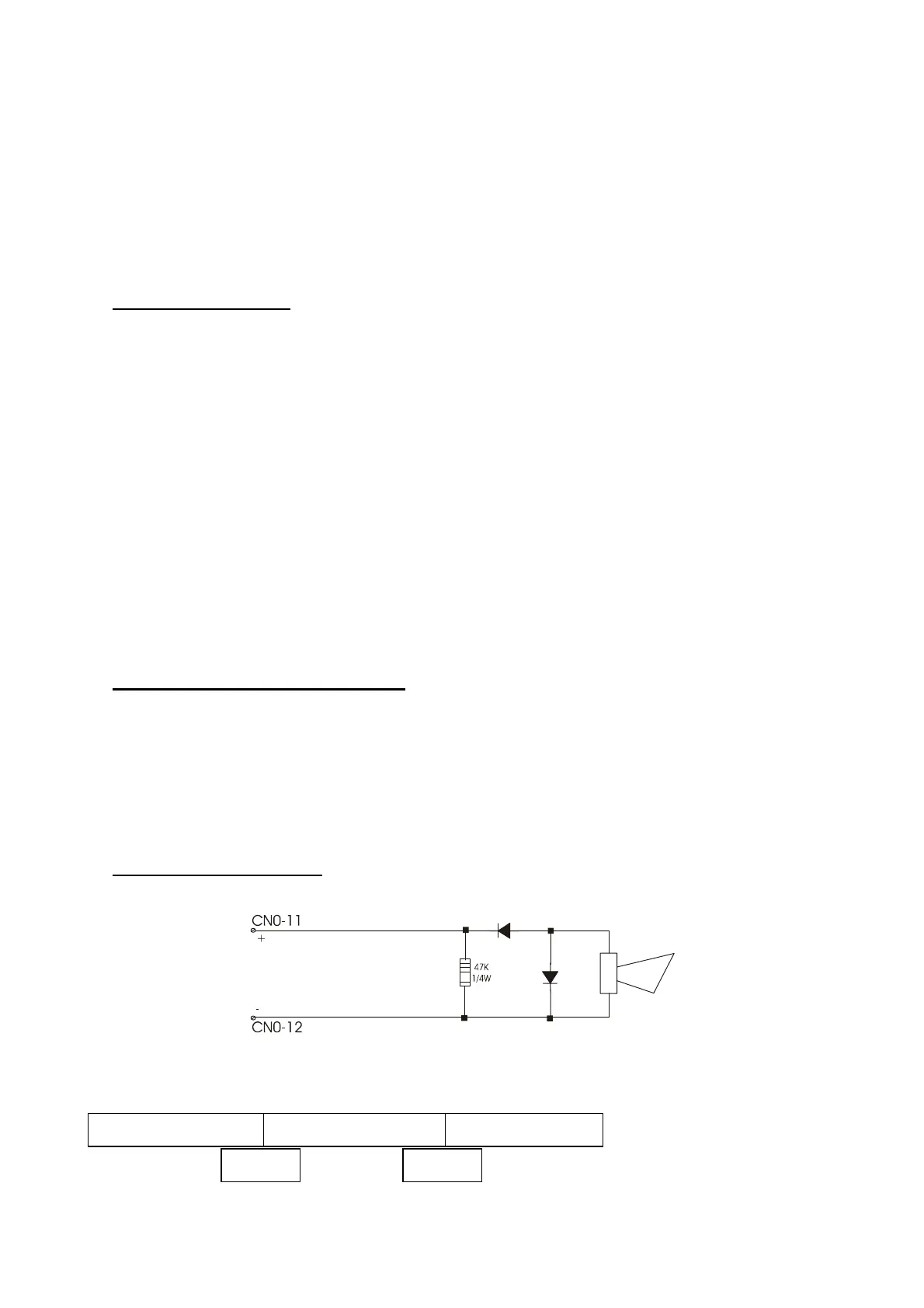
Connection of the Siren
Sounder output window
Not-polarized siren
End line
resistor
1N4004
STAND BY CUT SHORT CIRCUIT
21K 61K

 Loading...


