ID2000 Series Installation & Commissioning Manual
Installation - Panel Electronics
36997-433-000-5, Issue 5
May 2010
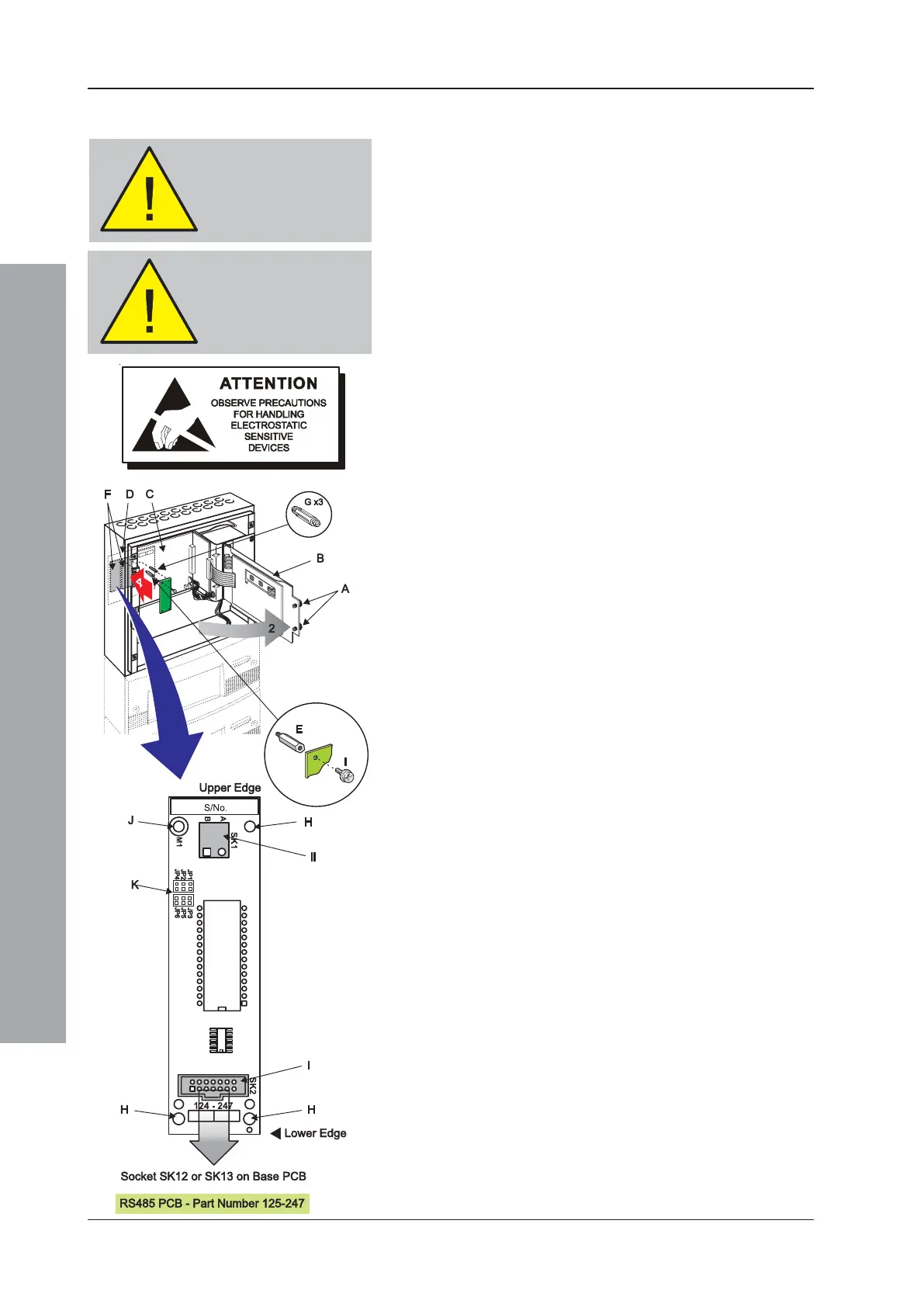
5.12 Isolated RS485 Interface PCB
The ID2000 Series Isolated RS485 Interface PCB
(PN: 124-247) enables the ID2000 Series Fire Control Panel
to be networked to other ID2000 Series control panels or for
connection to ID2000 Series repeater panels. The Isolated
RS485 Interface PCB is located adjacent to and at the left-
hand side of the Base PCB. The PCB is secured in position
using one metal spacer and three nylon spacers all provided
with the Isolated RS485 Interface PCB kit (PN: 020-479).
To fit the Isolated RS485 Interface PCB follow the
instructions below. Only one Isolated RS485 Interface
PCB is supported.
Before starting, make sure you have a PC back-up
of the panel’s current configuration data.
Ensure you take appropriate anti-static precautions
before undertaking this procedure.
With the front cover moulding(s) removed and power
disconnected, proceed as follows:
1 Using a suitable-sized coin, release the two quarter-turn
fasteners (A) located at the left-hand side of the main
chassis front door (B). Open the door to gain access to the
main chassis’ PCB enclosure (C) containing the Base PCB
(D).
2 Fit the metal spacer (E) through the Base PCB to the
top left fixing position of either PCB mounting location
(F). Tighten down fully using a 5.5mm Hex socket tool.
3 Fit the three supplied nylon snap-top spacers (G)
through the Base PCB by pushing them firmly into
place until they snap into position.
4 Observing anti-static precautions, remove the RS485
Interface PCB from its packaging. If, after inspection,
no damage has occurred in transit and with it correctly
orientated, carefully offer the PCB to the three snap-
top spacers. Take care when doing this to avoid
damaging the PCB. Working in a clockwise direction,
carefully push the PCB onto the snap-top spacers
(positions H) until the PCB is secure.
5 Use the M3 x 8mm SEM screw (I) to secure the
Isolated RS485 Interface PCB to the metal spacer
(position J).
6 Make the necessary wiring connections to the RS485
Interface PCB - see details below.
7 If no other PCBs require fitting, close and secure the
main chassis front door, re-connect mains power and
the batteries and replace the front cover moulding.
8 To replace the Isolated RS485 Interface PCB, first
reverse the above procedure, steps 4 to 7, and then
fit the replacement RS485 Interface PCB using steps
4 to 7.
Note: Refer to Section 6, Repeaters and Network, for
details of the jumpers (I).
WARNING -
Disconnect power
from the ID2000
Series panel
Make sure you have
a PC back-up of the
current
configuration data
 Loading...


