ID2000 Series Installation & Commissioning Manual
Installation - Cabling
17
997-433-000-5, Issue 5
May 2010
3.3 EMC Considerations
Following the above instructions and by using suitable
cables EMC problems will be avoided. In particularly
difficult EMC environments, or where non-preferred
cabling is used, it is possible to fit additional ferrite
suppressors (sleeves) to cables entering the control
panel.
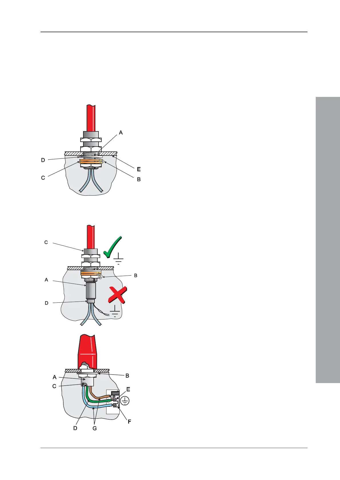
3.3.1 Screen Termination
Use the following method to terminate the cable screens:
Use a metal gland with slots (A) that allow the drain
wire or screen (B) to be clamped between flat washers
(C). Use a steel locking washer (D) between the brass
washers and the internal surface of the back box (E).
This will provide the best EMC termination. Suitable
glands are the CTX range available from CMP UK
Ltd. The part chosen should fit the 20mm knockouts.
3.3.2 Ferrite Sleeves (Optional)
Ferrite sleeves are not normally required with the ID2000
Series control panel. In difficult EMC environments, or
where non-preferred cables are used, optional ferrite
sleeves should be fitted to both the loop and sounder
wiring. The ferrite sleeves (A) are to be fitted over the
conductor(s) of each cable - and NOT over the screen
of the cable, which should pass outside of the sleeve.
They should be fitted as close as possible to the entry
point of the cable, i.e. as near as possible to the screen
termination (B) to the metal cable gland (C). The sleeve
should be held in place using a cable tie (D).
The ferrite sleeves are available for purchase from
NOTIFIER’s distributors (quote Part No. 538-143).
3.4 MICC Cables
MICC cables must be fitted with metal cable glands (A)
-use Type A2 glands. Use a steel locking washer (B) to
ensure good earthing continuity and correct termination
of the gland. In particular, the mains cable requires that
the cable gland (A) is fitted with an earth tail kit (C). The
earth tail kit must be connected, using an insulated wire
(D), to the panel safety earth connection (E) at the mains
termination block (F). The bare mains wiring from the
MICC cable must be suitably-insulated (G) and
terminated in accordance with appropriate local wiring
regulations.

 Loading...


