ID2000 Series Installation & Commissioning Manual
Installation - Panel Electronics
25
997-433-000-5, Issue 5
May 2010
5.4 Main Chassis
The ID2000 Series control panel main chassis provides
the following features:
a. System control and monitoring function PCBs
b. User-interface controls and system status indicators
c. Space provision for three loop-interface PCBs, panel
networking and interface hardware for external
equipment using serial communications.
The main chassis is simple to fit in the back box providing
these instructions are followed.
5.4.1 Main Chassis Configurations
Alternative PSU output ratings and mains standby battery
backup periods can be supported using different main chassis
options. Consequently, the main chassis can be fitted with:
a. The Kit PSU3A, or a
b. DTP/Booster Module for use with PSUs other than
the Kit PSU3A, which can be installed behind the
main chassis in a deep back box or in a separate
78Ah battery enclosure (refer to separate installation
instructions provided with enclosure).
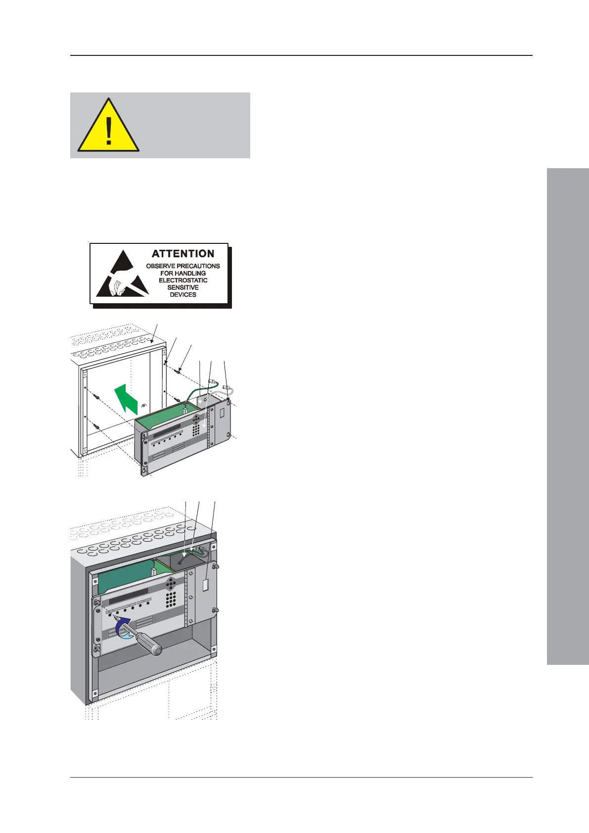
DO NOT fit the main chassis in the back box until the PSU
or DTP/Booster Module is in place (refer to Section 5.2, Kit
PSU3A or Section 5.3 DTP/Booster Module).
5.4.2 Procedure
Taking suitable anti-static precautions, such as wearing a
suitably-grounded wrist strap, remove all packaging from the
main chassis and ensure that it has not been damaged in
transit before proceeding any further. If no damage is evident,
and with the back box (A) secured to the wall in its chosen
location, ensure that either the Kit PSU3A (B) or DTP/Booster
Module (C) is fitted, then fit the main chassis (D) as follows:
1 Locate the four supplied M4 x 16 SEM screws (E) in
the back box holes (F).
2 Drive the four screws (E) in approximately half their length.
3 Taking suitable anti-static precautions, ensure the
main chassis is correctly orientated and offer the four
slotted holes (G) and locate on the threaded part of
the top two of the four screws (E) to avoid twisting
the chassis when securing in position.
4 Once the main chassis has been located on the SEM
screws (E) use a cross-headed screwdriver to tighten them.
5 Connect the earth lead (H) between the Kit PSU3A
top plate or DTP/Booster module and the earthing
blade terminals adjacent to the mains termination block
(not shown) in the back box. (See also step 5.2.1.2).
6 Connect the earth lead (I) between the main chassis earth
blade terminals and the earthing blade terminals adjacent
to the mains termination block (not shown) in the back box.
Note: The power supply ratings label is visable through
the aperture (J) in the main chassis.
DO NOT fit the main
chassis in the back box
until the PSU module has
been fitted!
E (x4)
F (x4)
G (x4)

 Loading...


