ID2000 Series Installation & Commissioning Manual
Commissioning
41
997-433-000-5, Issue 5
May 2010
8 Commissioning
8.1 Introduction
To bring the panel into an operational state ready for
configuration, follow the steps detailed below.
Information on how to configure the panel is given in
the ID2000 Series Panel Configuration Manual (ref. 997-
435-XXX).
The ID2000 Series panels provide comprehensive fault
monitoring and diagnostic routines which will prove very
useful during commissioning of the system. The
diagnostic messages, which are displayed on the LCD,
are listed in Appendix 1.
The following must be remembered about FAULT
conditions when commissioning the ID2000 Series
control panels.
Faults can result from:
a. A configuration mismatch between the installation
design and panel set up and/or external conditions,
such as the proximity of a strong RFI source, having
an adverse affect on the panel.
b. The failure of a panel module, such as the PSU or
Processor PCB.
Appendix 1 provides guidance to assist you in identifying
faults that fall into the categories described above.
8.2 Preliminary Checks
Before initial power connection, check that:
1 All circuit boards are correctly fitted.
2 All internal wiring connectors are properly mated.
3 The loop wiring and external sounder circuits have
NOT, at this stage, been connected.
4 Sounder circuits 3 and 4 are configured as relays if
so required.
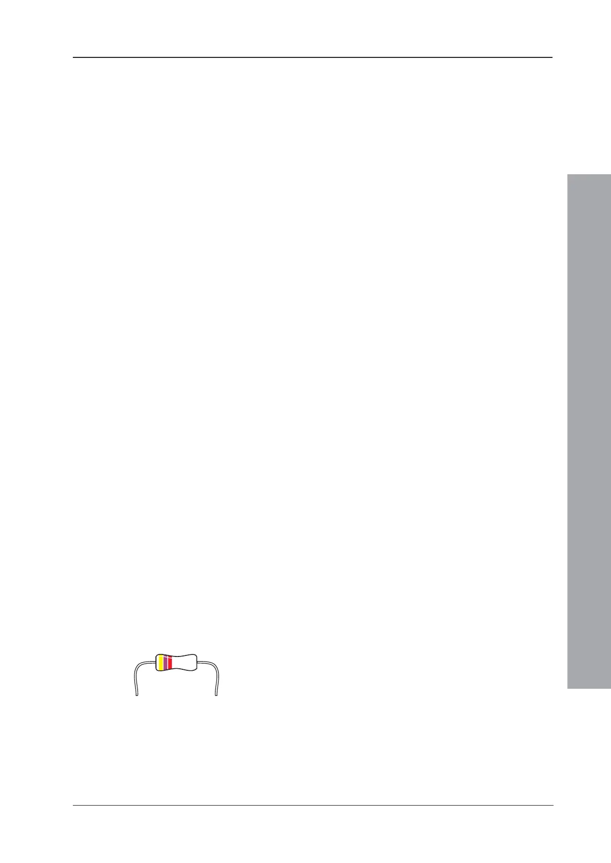
5 The 4k7 end-of-line resistors are connected to the
sounder outputs.

 Loading...


