ID2000 Series Installation & Commissioning Manual
Installation - Cabling
15
997-433-000-5, Issue 5
May 2010
3.1.1 Cable Terminations
This section provides some guidance on where to bring
cables into the back box for ease of termination.
a. The mains supply should be brought into the control
panel where the cable path to the mains termination
block is kept as short as possible.
b. All loop and ancillary cable terminations should be
brought into the panel at suitable positions to ensure
tails are kept as short as possible.
c. All loop and ancillary cable terminations should be
brought into the panel at suitable positions to ensure
tails are kept as short as possible.
d. A row of knockouts, ‘u’, should be left to provide
adequate mains supply input/signal cable
segregation.
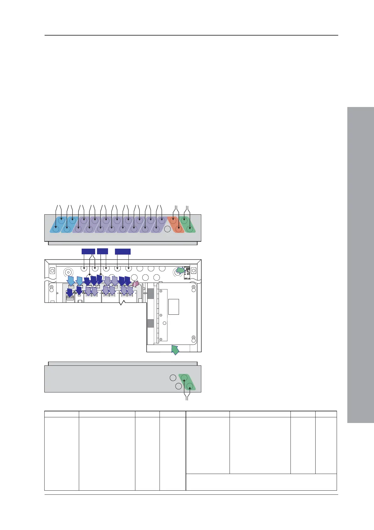
The drawing below shows recommended points of entry
so that cabling can meet these requirements:
e
i
h
g
f
a
e
d
b
l
k
c
n
m
p
r
o
q
s
Name Function Cable Knockouts
a. OUT 1 Sounder 2-core a
OUT 2 Sounder 2-core a
b. OUT 3 Sounder/Volt-free Contact 2-core b
OUT 4 Sounder/Volt-free Contact 2-core b
c. INPUT 1 Control Matrix 2-core Any Spare
INPUT 2 Control Matrix, Day/Night
Mode Remote 2-core Any Spare
d. AUX 1 Auxiliary output 2-core d
e. AUX 2 Auxiliary output 2-core e
f. LOOP 1 Loop circuit 1 OUT 2-core f
LOOP 1 Loop circuit 1 IN 2-core f
g. LOOP 2 Loop circuit 2 OUT 2-core g
LOOP 2 Loop circuit 2 IN 2-core g
Name Function Cable Knockouts
a. OUT 1 Sounder 2-core a
OUT 2 Sounder 2-core a
b. OUT 3 Sounder/Volt-free
Contact 2-core b
OUT 4 Sounder/Volt-free
Contact 2-core b
c. INPUT 1 Control
Matrix 2-core Any Spare
INPUT 2 Control
Matrix, Day/Night
Mode
Remote 2-core Any Spare
d. AUX
1 Auxiliary output 2-core d
e. AUX
2 Auxiliary output 2-core e
f. LOOP 1 Loop
circuit 1 OUT 2-core f
LOOP 1 Loop
circuit 1 IN 2-core f
g. LOOP 2 Loop
circuit 2 OUT 2-core g
LOOP 2 Loop
circuit 2 IN 2-core g
1-
2
3
NOT for the ID2002 Series Panels.
- Power supply cables (x2) and fault indication wiring.
- Recommended with internal PSU option.
1 -
2
3
NOT for the ID2002 Series Panels.
-
Power supply cables (x2) and fault indication wiring.
-
Recommended with internal PSU option.
Name Function Cable Knockouts
h. FAULT RELAY Fault relay outputs 2-core h
i. FIRE RELAY Fire relay outputs 2-core i
j. COVER OFF Not supported - -
k/l. RS232/RS485 Comms circuits 2-core k/l
m-r LOOPs 3/4,5/6,7/8 As item f. as item f. m-r
s. Fused Mains Block Termination of mains input 3-core s
t. External PSU DTP/Booster termination 3 x 2 cores t
u. Leave Spare Mains/signal wiring segregation - u
1
2
Name Function Cable Knockouts
h. FAULT RELAY Fault
relay outputs 2-core h
i. FIRE
RELAY Fire relay outputs 2-core i
j. COVER
OFF Not supported - -
k/l. RS232/RS485 Comms
circuits 2-core k/l
m-r LOOPs
3/4,5/6,7/8 As item f. as item f. m-r
s. Fused
Mains Block Termination of mains input 3-core s
t. External
PSU DTP/Booster termination 3 x 2 cores t
u. Leave
Spare Mains/signal wiring segregation - u
1
2
The drawing shows the recommended points
of entry so that cabling can meet these
requirements.
Panel with internal PSU
i. Base PCB cabling/wiring terminations
using top-face knockouts ‘a, b, f and g’.
ii. Base PCB cabling/wiring terminations
using rear knockouts ‘d, e, h and i’.
iii. RS232 or RS485 cabling terminations using
rear knockouts ‘k and l’.
iv. Loops 3/4, 5/6, 7/8 cabling using top face
knockouts ‘m/n, o/p and q/r’ respectively.
v. Power supply cable entry using knockouts
‘s’.
Panel with external PSU
As above except for item v above, which is
replaced with:
vi. DTP/Booster Module cabling using
knockouts ‘t’. See external PSU and DTP/
Booster Module instructions for details.

 Loading...


