ID2000 Series Installation & Commissioning Manual
Installation - Panel Electronics
24997-433-000-5, Issue 5
May 2010
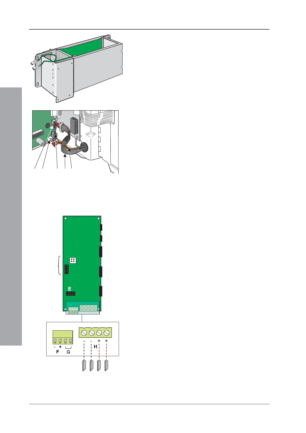
The illustration at left shows the DTP/Booster module
correctly located in the main chassis.
5.3.1.1 Main Chassis Wiring Connections
Once the DTP/Booster module is fitted to the main
chassis, the two wiring assemblies that are held by the
grommet should now be terminated on the Base PCB
connection sockets as follows:
a. The 10-way ribbon cable (A) is to be terminated at
socket SK18 (B).
b. The 4-wire power cable (C) is to be terminated at
socket SK21 (D).
Note: Connector (E) may not be fitted.
5.3.1.2 Other Wiring Connections
CAUTION: Before proceeding, refer to the cabling
instructions given in Section 3.1.
The following additional wiring must be connected:
a. If the DTP/Booster module is to be connected to an
internally-mounted PSU (other than the Kit PSU3A), fit
the supplied ribbon cable between the DTP/Booster
connector (E) and the PSU’s LED status indication
output connector. This connection is not used if the PSU
is mounted externally.
b. Connect a suitable cable (supplied with the PSU)
between the PSU Charger Inhibit connector (F) and
the equivalent connector on the PSU (on PSU
assemblies PN: 124-190 and 124-190-001, this
connector is labelled ALARM). Connect + to + and - to
-.
c. If the DTP/Booster module is to be connected to an
externally-mounted PSU, connect a suitable cable
between the COMMON FAULT connector (G) and
the Normally Open and Common connections of the
equivalent connector on the PSU.
d. Connect suitable (high-current) cables (if PSU is
internal, use cables supplied with the PSU) between
the Power connector (H) and the power supply unit.
Connect + to + and - to - (may be labelled 0V).
e. CAUTION! If using an externally-mounted PSU,
it is essential that an electrical safety earth
connection is made to the back box of the ID2000
panel. This connection should be routed with the
other PSU cables from the external battery box.

 Loading...


