ID3000/ID2000 Fire Panel Configuration Tool Manual
Control Matrix
4 - 2 997-291, Version 3.05
November 2010
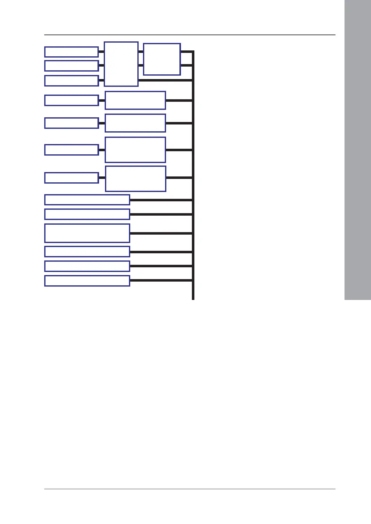
4.1.2 Input Event Statement
A simplified diagram showing valid inputs is
given below. More detail is given in
Section 4.3.1. For inputs ‘Alarm’, ‘Pre-alarm’
and ‘Fault’ the output is latched, otherwise it is
unlatched.
a. If two devices co-incidence and a specific type
are applied, the type check is carried out on
the second device only (the one which
completes the co-incidence). It is best to avoid
this combination and arrange for all devices
to be included in the co-incidence group to be
put in a specific zone or cell. If the input is
‘Alarm’, zone co-incidence is also available.
3+ devices: type check applies to all.
b. Types are: Any (no restriction), Heat,
Ionisation, Optical, Any analogue sensor,
MCP, VIEW, Smoke + Heat*, Any sensor +
MCP*, VIEW + any sensor*, or MULTI.
(*these are co-incidence combinations).
c. From AUX module. Non-fire also available from
panel Base PCB INPUT 1 and 2 with no
further selections except (ID
2
net only) the panel
number. These can be used for class change;
their outputs can only be active on closing
contact input, not on opening contact input.
d. If a remote fire output is configured, its
disablement is also available as an input to
the control matrix.
e. See Section 4.1.4.
f., g., h & i. are described on the next page.
SPECIFY
DEVICE,
ZONE(s),
CELL(s)
OR VIP*
COINCI-
DENCE (a.),
TYPE (b.)
ACTIVATING MCP WHILE ITS
ZONE IS IN WALK TEST (f.)
I
N
P
U
T
SELECT ZONE OR
GENERAL PANEL
SELECT ZONE,
GENERAL PANEL,
OR SOUNDERS (d.)
SELECT SYSTEM &
BEFORE/AFTER
DELAY (e.)
* = VIRTUAL INPUT POINT, see Section 1.5.11.
 Loading...


