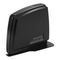
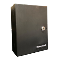
5NFN Gateway Installation & Operation Manual - P/N: 52306:Rev: D 06/01/07
Table of Contents
Section 1 NFN Gateway Overview........................................................................................... 7
1.1: Product Description .......................................................................................................................................7
Table 1.1 NFN Compatibility Table.......................................................................................................7
1.2: NFN Gateway System Architecture ..............................................................................................................8
Figure 1.1 Direct Panel Gateway System...............................................................................................8
Figure 1.2 ONYXWorks
®
System Example 1- A Single NFN Network...............................................9
Figure 1.3 ONYXWorks
®
System Example 2 - Multiple NFN Networks ..........................................10
Figure 1.4 Example NFN Gateway Network .......................................................................................11
1.3: Overall Gateway Configuration Process Flow Diagram .............................................................................13
Figure 1.5 Overall Gateway Configuration Process Flow Diagram.....................................................13
1.4: Agency Listings ...........................................................................................................................................14
1.4.1: Environmental Requirements ............................................................................................................14
1.5: Related Documentation ...............................................................................................................................15
Section 2 NFN Gateway Embedded Installation .................................................................. 17
2.1: Required Equipment ....................................................................................................................................17
2.2: NFN Gateway Installation Overview ..........................................................................................................18
2.2.1: Gateway Installation Process Overview Flow Diagram....................................................................18
Figure 2.1 Gateway Installation Process Flow Diagram ......................................................................18
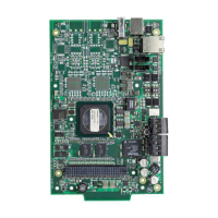
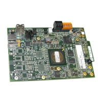
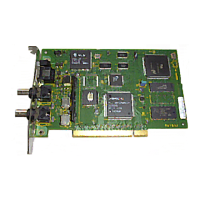
2.2.2: NFN Gateway PC Board Layout.......................................................................................................19
Figure 2.2 NFN Gateway PC Board.....................................................................................................19
2.3: CAB3/CAB4 Cabinet Installation ...............................................................................................................20
Figure 2.3 CAB-3/CAB-4 Series Installation Document, 15330.........................................................20
2.4: NFN Gateway Hardware Installation ..........................................................................................................21
Figure 2.4 NFN Gateway Assembly Installation Diagram ..................................................................21
2.5: Network Communication Module Installation ............................................................................................22
Figure 2.5 NCM W/F PC Board Installation Document ......................................................................22
Figure 2.6 NCM-W/F Power Connection ............................................................................................22
2.6: NFN Gateway Power Connection ...............................................................................................................23
Table 2.1 Power Supply Specifications................................................................................................23
Figure 2.7 NFN Gateway Power Connection.......................................................................................23
2.7: NFN Gateway Cable Connections...............................................................................................................24
2.7.1: IP Cable Connections ........................................................................................................................24
Figure 2.8 IP Cable Connection ...........................................................................................................24
2.7.2: Gateway Network Cable Connection ................................................................................................25
Figure 2.9 DB-9 to NUP Connection ...................................................................................................25
2.8: Optional NFN Gateway Voice Paging .........................................................................................................26
2.8.1: About Voice Paging...........................................................................................................................26
2.8.2: Microphone and Public Address Amplifier Connections..................................................................26
Figure 2.10 Gateway Sound Cable Installation....................................................................................26
Figure 2.11 Public Address Amplifier Connections to Gateway Sound Cable....................................27
Section 3 NFN Gateway Configuration ................................................................................. 29
3.1: Gateway Configuration Process Overview Flow Diagram .........................................................................29
Figure 3.1 Gateway Configuration Process Flow Diagram..................................................................29
3.2: Configuration PC Preparation......................................................................................................................30
3.2.1: Install the NFN Config Tool on the Configuration PC .....................................................................30
3.2.2: Connect the Configuration PC to the NFN Gateway ........................................................................30
Figure 3.2 Configuration PC Direct Connection..................................................................................31
Table 3.1 Cross Over Cable (568B) .....................................................................................................31
3.2.3: Add the IP Subnet of the NFN Gateway into the Configuration PC.................................................32
Figure 3.3 TCP-IP Address Window....................................................................................................32
3.3: NFN Gateway Connection...........................................................................................................................33
3.3.1: Default Gateway Connection.............................................................................................................33
3.4: NFN Gateway Configuration Procedure .....................................................................................................34

 Loading...
