Installation Instruction VARIODYN
®
D1 System
FB 798663.GB0 / 05.19 35
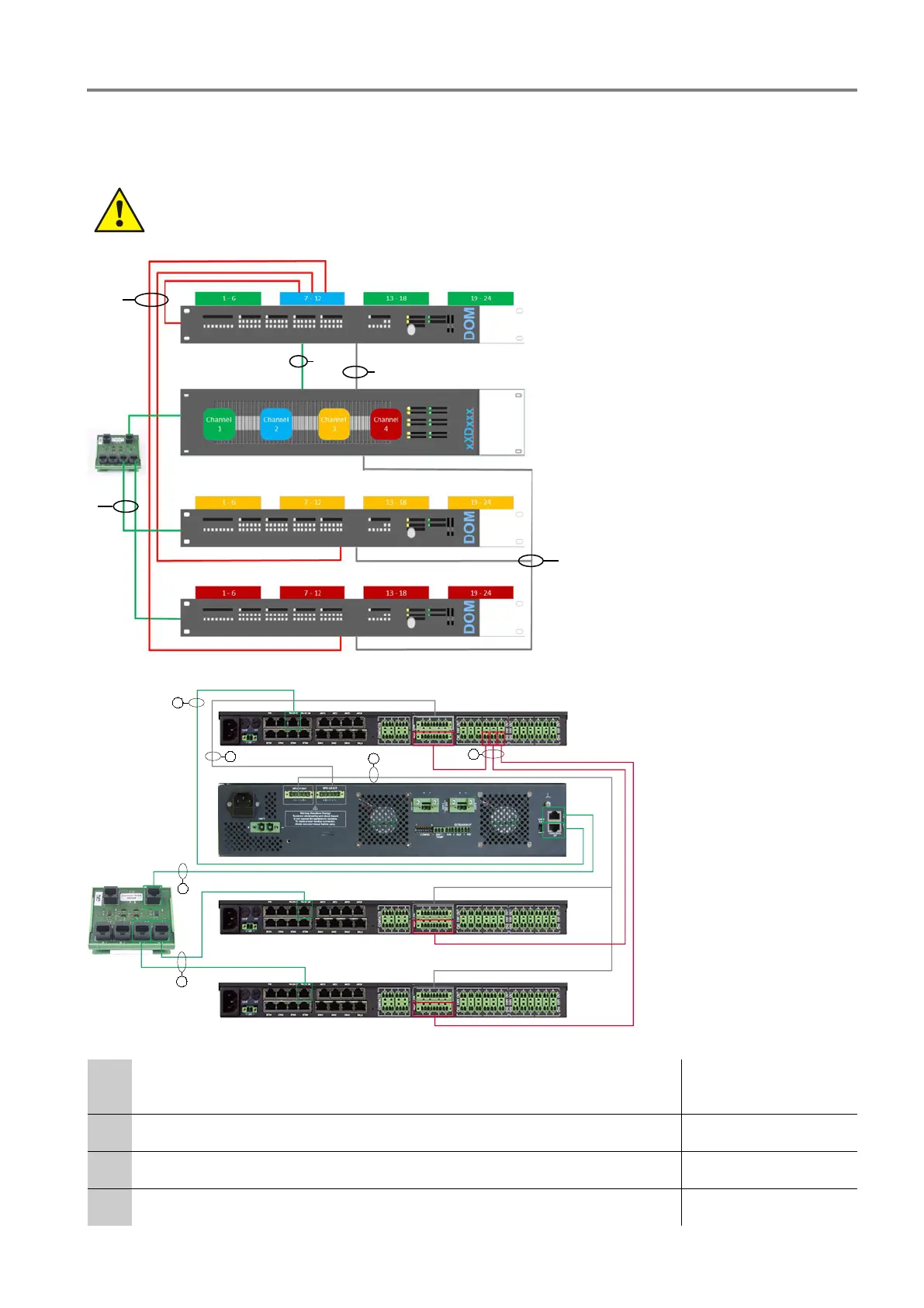
6.1.6 Application 1-24 – Variant 1
Application 1–24 – variant 1, operates with three DOM, each with an amplifier channel. The amplifier channel
supplies all the loudspeaker lines of the DOM = 66 zones per amplifier + backup for all three DOM.
• This application, including backup on channel 2, is solely permitted with amplifiers 4XD125B
and/or 4XD250B.
•
The spare connections on the connection board must not be used to connect additional
amplifiers.
Fig. 25: Overview application 1-24 – Variant 1
PA
DOM 2
DOM 3
DOM 1
Connection
Board
583369
1
1
2
3
4
1
Fig. 26: Input / output connection
Input cable DOM amplifier
(0,5 m, green) audio frequency (AF), control to power amplifier (PA)
583491 or 583491A
Output cable1-18 (1 channel up to 6 or 18 lines) 583430
Output cable 1-24 (2 channels each up to 24 lines) 583432
Backup cable RC 41 VARIODYN
®
D1 583441.10
 Loading...