Installation Instruction VARIODYN
®
D1 System
50 FB 798663.GB0 / 05.19
Connecting universal interface module (UIM) DOM
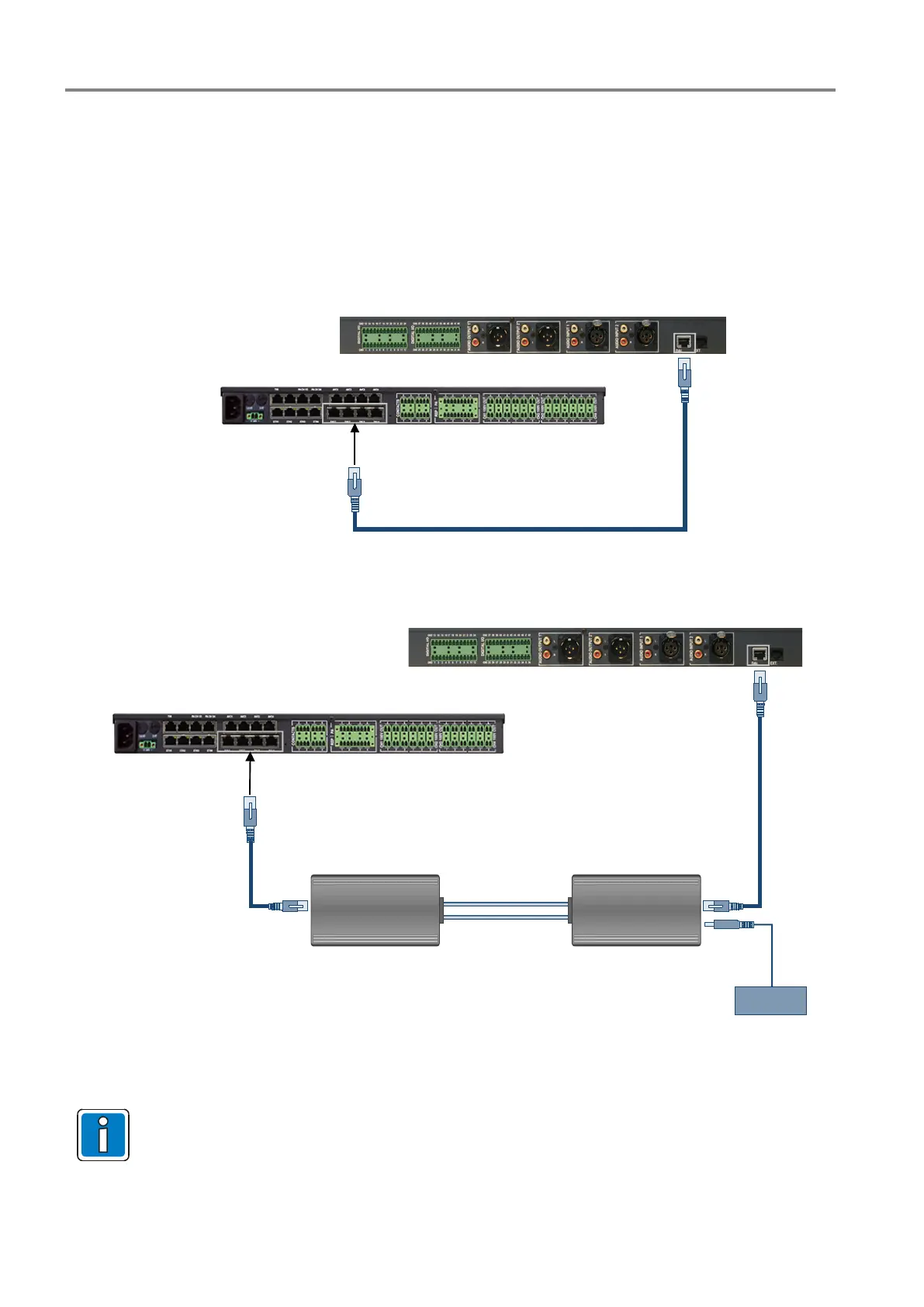
1. Use a patch cable CAT5 blue to connect the DAL connection of the DOM and the DAL connection of the UIM.
2. If external control inputs or outputs are present, wire them to the terminals of the UIM .
3. If external audio inputs or outputs are present, connect them to the CINCH or XLR sockets of the
UIM and .
4. XLR socket: Pin 1 = shielding, pin 2 = tone wire A, pin 3 = tone wire B.
UIM
DAL 1-4
DOM
CAT5, max. 300 m
Fig. 41: Connection of the UIM to the DOM using CAT5 cable
DAL 1-4
DOM
OIM
(DCS-O)
max. 10 m max. 10 m
UIM
Fibre optics cable
max. 2000 m
(Multimode)
Power supply
or
via 24 V DC from system
(Part No. 583316.21)
(Part No. 583317.21)
Fig. 42: Connection of the UIM to the DOM via fibre optic cable (FOC)
See chapter Fehler! Verweisquelle konnte nicht gefunden werden. for detailed information on the
fibre optic converter and the required external power supply
 Loading...