CHAPTER 11: SUMMARIES OF PARAMETER SETTINGS
107 63-4528—04
a
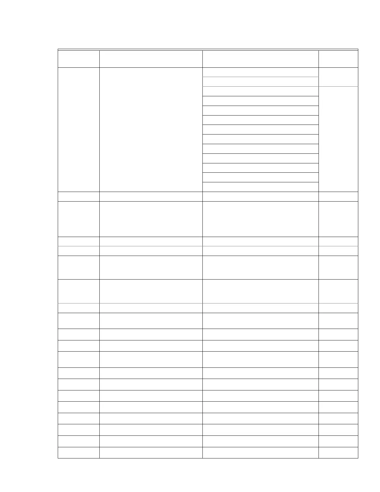
03-20 Multi-function Output 2 (AFM2)
1: Frequency command (Hz)
0
2: Motor speed (Hz)
3: Output current (rms)
100
4: Output voltage
5: DC Bus voltage
6: Power factor
7: Power
9: AVI1 %
10: ACI %
11: AVI2 %
20: CANopen analog output
22: Communication card analog output
23: Constant voltage output
a
03-21 Gain for Analog Output 2 (AFM2) 0~500.0% 100
a
03-22
Analog Output 2 Value in REV
Direction (AFM2)
0: Absolute output voltage
1: Output 0V in REV direction; output 0-10V
in FWD direction
2: Output 5-0V in REV direction; output 5-
10V in FWD direction
0
a
03-23 Display Low pass Filter (AFM1) 0.001~65.535 seconds 0
a
03-24 Display Low pass Filter (AFM2) 0.001~65.535 seconds 0
a
03-25 AVI1 Selection
0: 0-10V
1: 0-20mA
2: 4-20mA
0
a
03-26 ACI Selection
0: 4-20mA
1: 0-10V
2: 0-20mA
0
a
03-27 Status of PLC Output Terminal Monitor the status of PLC output terminals Read Only
03-28 AFM2 0-20mA Output Selection
0: 0-20mA
1: 4-20mA
0
03-29 AFM1 DC output setting level 0.00~100.00% 0.00
03-30 AFM2 DC Output Setting Level 0.00~100.00% 0.00
03-31 AFM1 0-20mA/4-20mA selection
0: 0~20mA
2:4-20mA
0
03-32 AI calculated selection 0~7 1
03-33 AVI Point1 – voltage 0.00 ~ 10.00 / 0.00~20.00 0.00
03-34 AVI Point 1- Hz 0.00 ~ 600.00Hz 20.00
03-35 AVI Point 2- V/mA 0.00 ~ 10.00 / 0.00 ~ 20.00 10.00/20.00
03-36 AVI Point2- Hz 0.00 ~ 600.00Hz 60.00
03-37 AVI Point 3 – V/mA 0.00 ~ 10.00 / 0.00 ~ 20.00 10.00/20.00
03-38 AVI Point 3- Hz 0.00 ~ 600.00Hz 100
03-39 ACI Point 1 – V/mA 0.00 ~ 10.00 / 0.00 ~ 20.00 0.00/4.00
Table 4. Analog Input/Output Parameter
Parameter Explanation Settings
Factory
Setting
 Loading...


