CHAPTER 12: DESCRIPTION OF PARAMETER SETTINGS
229 63-4528—04
10 Pump Parameter ~ The parameter can be set during operation.
• In this mode, VFD CORE can control up to 8 motors at a time. The total number of the motors can be determined by Pr.10-01.
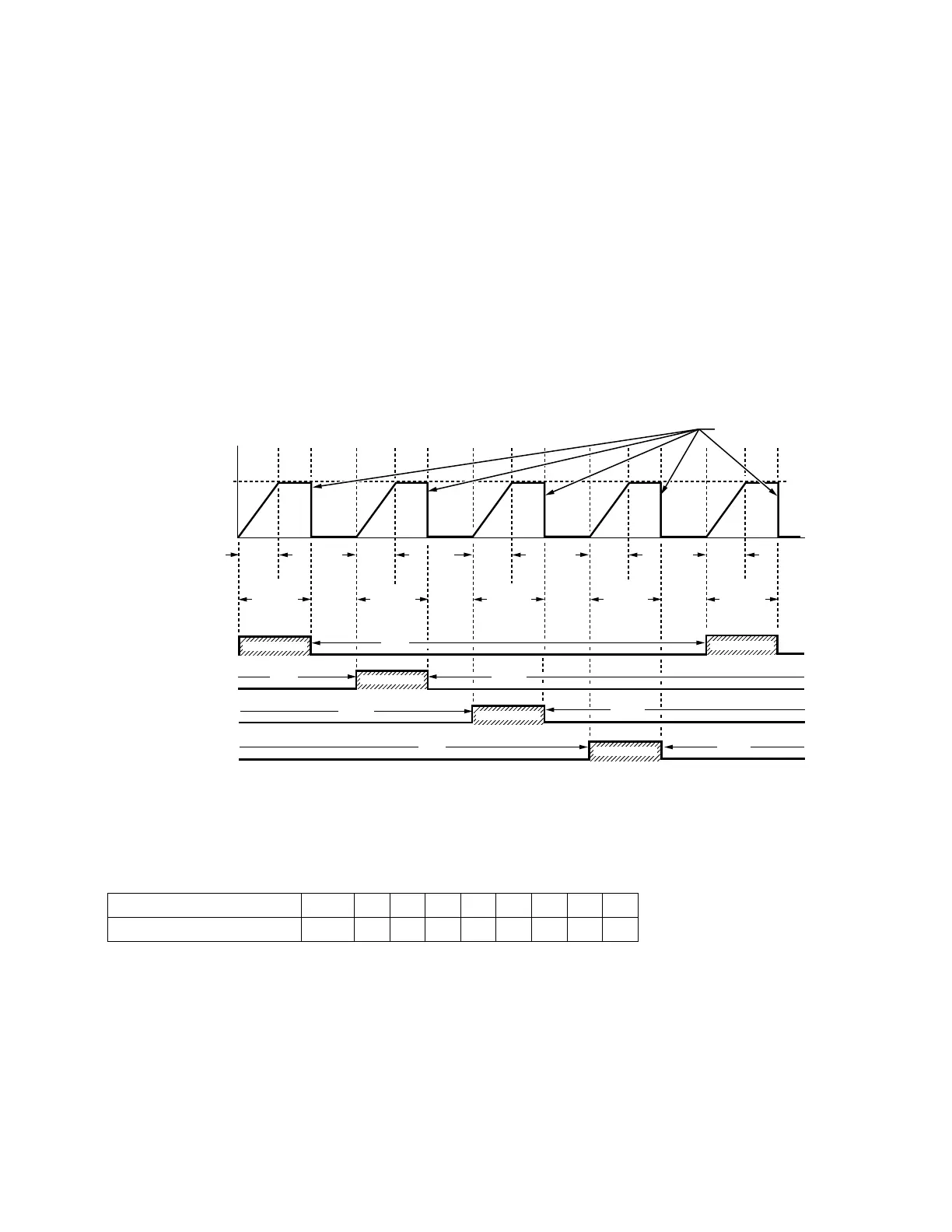
In accordance with the Fixed Time Circulation of Pr10-02, you can adjust the switching time between Start/Stop of each motor.
That means when an operating motor reaches the time setting of Pr10-02, VFD CORE will stop that motor. Then after the
delay time setting of Pr10-03, next motor will start operating. See diagram below.
Fig. 2. Sequential Diagram of the Fixed Time Circulation (by time)
• Disable Motors’ Output
Set the Multifunction Input Commands as Disable Motors’ Output can stop corresponding motors. The settings are:
When a motor’s output is disabled, this motor will park freely.
10 - 00 Circulative Control
Factory Setting: 0
Settings 0: No operation
1: Fixed Time Circulation (by time)
2: Fixed Quantity
3: Fixed quantity control
4: Fixed Time Circulation + Fixed Quantity Circulation
5: Fixed Time Circulation + Fixed Quantity Control
P02-01~P02-06= 60 61 62 63 64 65 66 67 68
Disable Motors’ Output ALL12345678
M33766
TIME
PR.10-02
ACC.
TIME
P.01-12
ACC.
TIME
P.01-12
ACC.
TIME
P.01-12
ACC.
TIME
P.01-12
PR.10-03 PR.10-03 PR.10-03 PR.10-03 PR.10-03PR.10-02 PR.10-02 PR.10-02 PR.10-02
COAST TO STOP
OFF
OFF
OFF
OFF
OUTPUT
FREQ.
VFD CORE
OPERATION
MOTOR 1
MOTOR 2
MOTOR 3
MOTOR 4
FREQUENCY
ACC.
TIME
P.01-12
BY VFD CORE
OFF
OFF
OFF
BY VFD CORE
BY VFD CORE
BY VFD CORE
BY VFD CORE
 Loading...


