CHAPTER 8: INSTALLATION OF THE OPTION CARDS
77 63-4528—04
Environment Specification
Installation
LED Indicator and Troubleshooting
There are 2 LED indicators on PROFIBUS DP COMMUNICATION CARD. POWER LED displays the status of the working power.
NET LED displays the connection status of the communication.
Noise immunity
ESD(IEC 61800-5-1,IEC 6100-4-2)
EFT(IEC 61800-5-1,IEC 6100-4-4)
Surge Teat(IEC 61800-5-1,IEC 6100-4-5)
Conducted Susceptibility Test (IEC 61800-5-1,IEC 6100-4-6)
Operation/storage
Operation: -10°C ~ 50°C (Temperature), 90% (Humidity)
Storage: -25°C ~ 70°C (Temperature), 95% (Humidity)
Shock/vibration
resistance
International standardIEC61131-2, IEC68-2-6 (TEST Fc) / IEC61131-2 & IEC 68-2-27(TEST Ea)
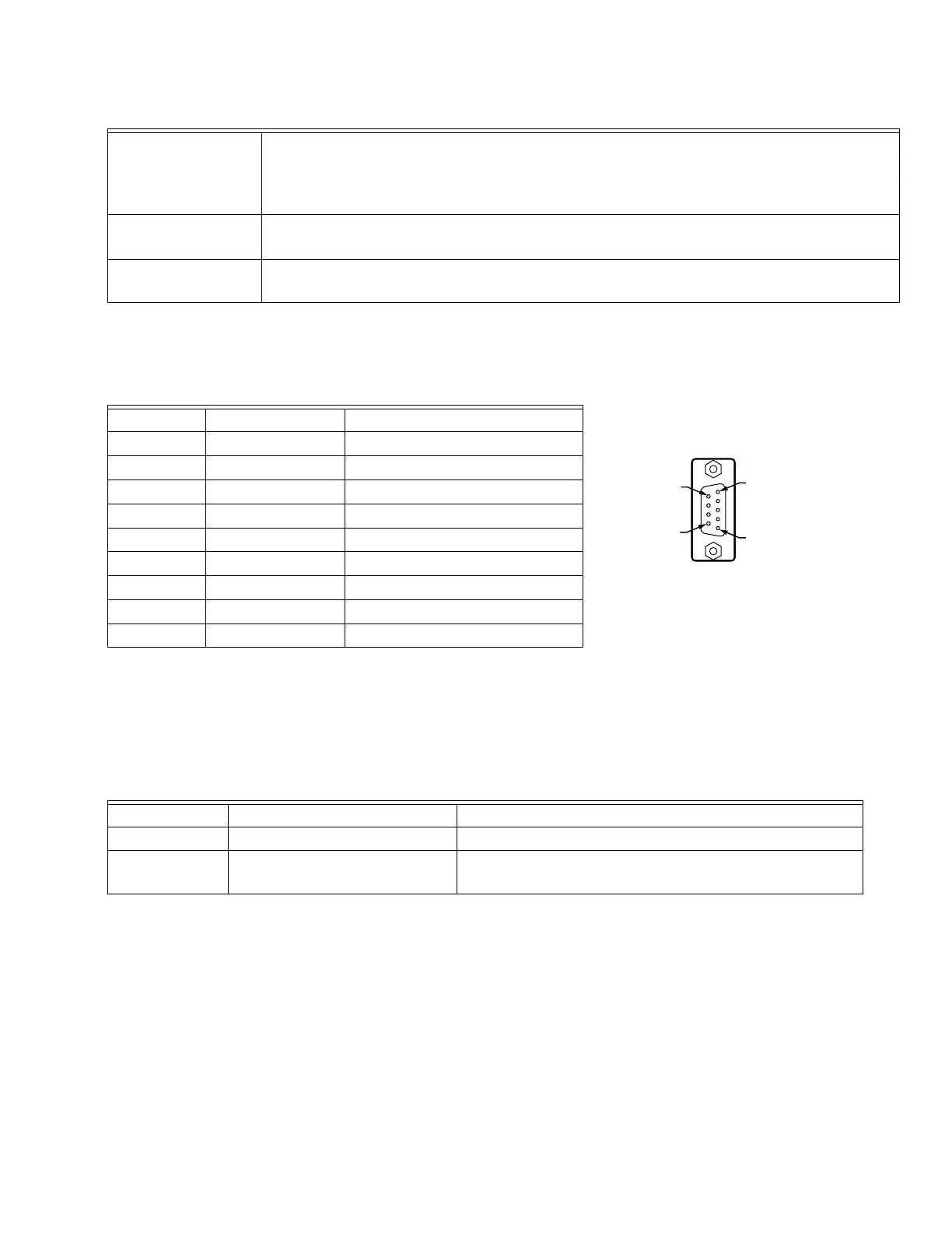
PROFIBUS DP Communication Connector: Definition of pins
Pin Name Definition
1- Not defined
2- Not defined
3 Rxd/Txd-P Sending/receiving data P(B)
4- Not defined
5 DGND Data reference ground
6 VP Power voltage – positive
7- Not defined
8 Rxd/Txd-N Sending/receiving data N(A)
9- Not defined
POWER LED
LED status Indication Action
Green light on Power supply in normal status. No action required
Off No power
Check if PROFIBUS DP COMMUNICATION CARD and VFD
are properly connected.