Model 204B
\
I
FEEDBACK AMPLIFIERS EMITTER
RC
Section
Paragraphs
4-1
to 4-10
ATTENUATOR
SECTION
PRINCIPLES
OF
OPERATION
BRIDGE
(RIOA,B,C2,C7)
4-1.
INTRODUCTION.
FOLLOWERS
!
,
,
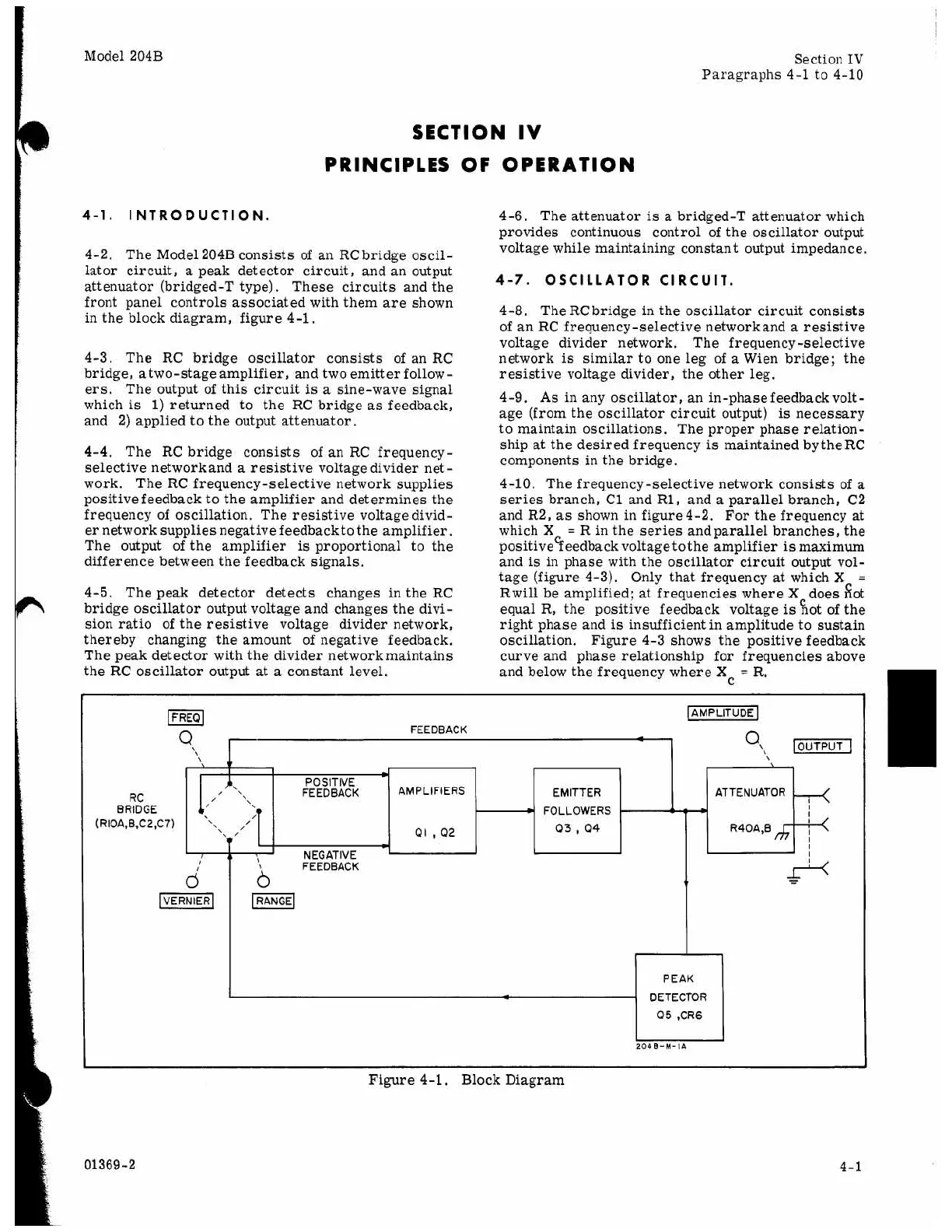
4-2.
The Model 204B consists of an RC bridge oscil-
lator circuit,
a
peak detector circuit, and an output
attenuator (bridged-T type). These circuits and the
front panel controls associated with them are shown
in the block diagram, figure 4-1.
4-3. The RC bridge oscillator consists of an RC
bridge, atwo-stage amplifier, and two emitter follow-
ers.
The output of this circuit
is
a
sine-wave signal
which
is
1)
returned to the RC bridge as feedback,
and 2) applied to the output attenuator.
4-4.
The RC bridge consists of an RC frequency-
selective networkand
a
resistive voltage divider net
-
work. The RC frequency-selective network supplies
positive feedback to the amplifier and determines the
frequency of oscillation. The resistive voltage divid-
er network
supplies negative feedback to the
amplifier.
The output of the amplifier
is
proportional to the
difference between the feedback signals.
4-5. The peak detector detects changes in the RC
bridge oscillator output voltage and changes the divi-
sion ratio
of
the resistive voltage divider network,
thereby changing the amount of negative feedback.
The peak detector with the divider networkmaintains
the RC oscillator output at
a
constant level.
PEAK
DETECTOR
Q5 ,CR6
4-6. The attenuator
is
a bridged-T attenuator which
provides continuous control of the oscillator output
voltage while maintaining constant output impedance.
4-7.
OSCILLATOR CIRCUIT.
4-8, The RC bridge in the oscillator circuit consists
of an RC frequency-selective networkand a resistive
voltage divider network. The frequency-selective
network
is
similar to one leg of
a
Wien bridge; the
resistive voltage divider, the other leg.
4-9.
As
in any oscillator, an in-phase
feedback volt-
age (from the oscillator circuit output)
is
necessary
to maintain oscillations. The proper phase relation-
ship at the desired frequency
is
maintained by
the
RC
components in the bridge.
4-10. The frequency-selective network consists of
a
series
branch, C1 and R1, and
a
parallel branch, C2
and R2,
as
shown in figure4-2. For the frequency at
which X
=
R in the series andparallel branches, the
positive
feedback
voltage to the amplifier
is
maximum
and
is
in phase with the oscillator circuit output vol-
tage (figure 4-3). Only that frequency
at
which
X
=
Rwill be amplified; at frequencies where Xcdoes fiot
equal R, the positive feedback voltage
is
not of the
right phase and
is
insufficient in amplitude to sustain
oscillation. Figure 4-3 shows the positive feedback
curve and phase relationship for frequencies above
and below the frequency where X
=
R.
C
01369-2
Figure 4-1, Block Diagram
4-1