Section
V
Paragraphs 5-31 to 5-35
b. Set Model 204B RANGE to X100, VERMER to
center of its range, and AMPLITUDE to maximum
clockwise position,
c. Set FREQ. to 56 (5.6 kc).
d. Lock FREQ. dial shaft with
a
number 8-32
socket set screw (dial shaft locking screw) which in-
serts into threaded hole on top of dial shaft housing
.
e.
Loosen potentiometer (pot) shaft locknut, fig-
ure 5-5a, and adjust pot by turning pot arm to obtain
a
5.6-kc output,
f,
Tighten pot shaft locknut, and loosen dial shaft
locking screw.
g. Set FREQ. to 5 (500 cps) and tightendial shaft
locking screw.
h. Loosen dial shaft locknut and adjustdial cam
by turning cam to obtain
a
500-cps output.
i.
Tighten dial shaft locknut and loosen dial shaft
locking screw.
j.
Repeat steps c through
i
untilfrequencies
are
within approximately
rtl%.
k. Set RANGE to XlOK, FREQ. to 5 (50 kc), and
adjust C8 (figure 5-6) to obtain
a
50-kc output.
m. Set FREQ. to 56 (560 kc), and adjust C15
(figure 5-4) to obtain
a
560-kc output.
If
necessary,
change the value of C14 for proper range of C15.
Check gain control voltage according to
steps
a
and b of paragraph
5-28.
Note
n. All frequencies across the band should be
within
*3%.
5-31.
REPLACEMENT PROCEDURES.
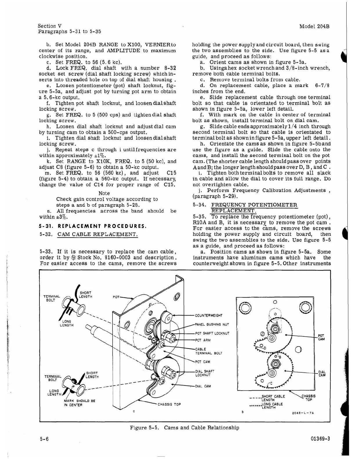
5-32. CAM CABLE REPLACEMENT.
5-33.
If
it
is
necessary to replace the cam cable,
order
it
by
@
Stock No. 8160-0003 and description.
For easier access to the cams, remove the screws
Model 204B
holding the power supply and circuit board, then swing
the two assemblies to the side. Use figure 5-5
asa
guide, and proceed
as
follows:
a.
Orient cams
as
shown in figure 5-5a.
b. Using
a
hex socket wrenchand 3/8-inch wrench,
c. Remove terminal bolts from cable.
d. On replacement cable, place
a
mark 6-7/8
inches from the end,
e.
Slide replacement cable through one terminal
bolt
so
that
cable
is
orientated to terminal bolt
as
shown in figure 5-5a, lower left detail.
f.
With mark on the cable in center of terminal
bolt
as
shown, install terminal bolt
on
dial cam.
g. Slide cable ends approximately 1/4 inch through
second terminal bolt
so
that cable
is
orientated to
terminalbolt
as
shown infigure 5-5a, upper left detail.
h. Orientate the cams
as
shown in figure 5-5band
use the figure
as
a
guide. Slide the cable onto the
cams, and install the second terminal bolt on the pot
cam. (The shorter cable length shouldpass over points
Aand
B;
the longer length should pass over
D,
B
,
and C
.
i.
Tighten both terminal bolts to remove all slack
in cable and allow the dial to cover its full range.
Do
not overtighten cable.
j,
Perform Frequency Calibration Adjustments
,
(paragraph 5-29).
remove both cable terminal bolts.
5-34. FREQUENCY POTENTIOMETER
REP LAC EM ENT.
5-35. To replace the frequency potentiometer (pot),
RlOA and
B,
it
is
necessary to remove the pot cam
.
For easier access to the cams, remove the
screws
holding the power supply and circuit board, then
swing the two assemblies to the side. Use figure 5-5
as
a
guide, and proceed
as
follows:
a.
Position cams
as
shown in figure 5-5a. Some
instruments have aluminum cams which have the
counterweight shown in figure 5-5. Other instruments
SHORT
TERMINAL LENGTH
.
.
SHORT
TERMINAL LENGTH
--
LONG
LENGTH
COUNTERWEIGHT
PANEL BUSHING NUT
POT SHAFT LOCKNUT
POT ARM
CABLE
TERMINAL BOLT
POT CAM
DIAL SHAFT
LOCKNUT
DIAL CAM
SHOULD
BE
IN CENTER
CHASSIS TOP
WT
CPM
DIAL
CAM
.......
LONG CABLE
LENGTH
b
Figure 5-5. Cams and Cable Relationship
5-6 01369-3