Section
V
Paragraphs 5-8 to 5-9
f.
Set FREQ. dial to 50, counter should read 20.0
*O.
6 milliseconds.
g. Set RANGE to XlOand FREQ. dial to 5, counter
should read the same
as
step
f.
h. Repeat steps
e
and
f
withRANGE atX10. Coun-
ter
should read 5.00
*O.
15 milliseconds and 2.00
f0.06 milliseconds respectively.
i.
Set frequency counter function switch to FRE-
QUENCY
(.
1).
j.
Complete check by setting RANGE switch and
FREQ. dial
as
shown in table 5-2, columns one and
two. The counter reading should be
as
shown
in
column three
.
Table 5-2. Dial Accuracy
Range
Switch
XlOO
XlOO
XlOO
X1 K
X1K
X1K
X1 OK
X1 OK
X1 OK
Freq.
Dial
5
20
50
5
20
50
5
20
50
500 cps
k
15 cps
2000 cps
i
60
cps
5000 cps
f
150 cps
5 kc
i
150 cps
20 kc
i
600
cps
50 kc
f
1.5 kc
50 kc
f
1.5 kc
200 kc
i
6
kc
500 kc
f
15 kc
5-8. FREQUENCY RESPONSE AND OUTPUT
VOLTAGE CHECK.
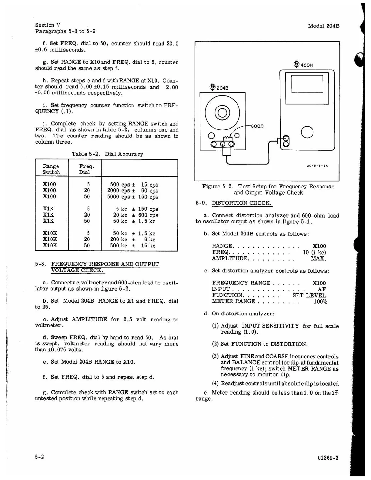
a.
Connect
ac
voltmeter and 600-ohm load to oscil-
lator output
as
shown in figure 5-2.
to 25.
b. Set Model 204B RANGE to X1 and FREQ. dial
c.
Adjust AMPLITUDE for 2.5 volt reading on
voltmeter.
d. Sweep FREQ.
dial
by hand to read 50. As dial
is
swept, voltmeter reading should not vary more
than
&O.
075 volts.
e.
Set Model 204B RANGE to X10.
f.
Set FREQ. dial to 5 and repeat step d.
g. Complete check with RANGE switch
set
to each
untested position while repeating step d.
Model 204B
0
2040
@400H
2040
-S
-SA
Figure 5-2. Test Setup for Frequency Response
and Output Voltage Check
5-9.
DISTORTION CHECK.
a.
Connect distortion analyzer and 600-ohm load
to oscillator output
as
shown in figure 5-1.
b. Set Model 204B controls
as
follows:
RANGE.
.............
XI00
FREQ..
...........
10
(1
kc)
AMPLITUDE. MAX.
.........
c. Set distortion analyzer controls
as
follows:
FREQUENCY RANGE.
.....
XlOO
INPUT..
.............
AF
FUNCTION.
.......
SET LEVEL
METER RANGE
.........
100%
d. On distortion analyzer:
(1)
Adjust
INPUT
SENSITIVITY for full scale
(2) Set FUNCTION to DISTORTION.
(3) Adjust FINE and COARSE frequency controls
and BALANCE control for dip
at
fundamental
frequency
(1
kc); switch METER RANGE
as
necessary to monitor dip.
(4) Readjust controls untilabsolute dip
is
located
e.
Meter reading should be
less
than
1.0
on the
1%
reading (1.0).
range.
5-2
01369-3