W
Model 204B
Section I1
Paragraphs
2-1
to 2-14
2
-1.
INSPECTION.
SECTION
II
INSTALLATION
2-2.
Unpack the instrument upon receipt and inspect
it
for signs of physical damage such
as
scratched
surfaces, broken knobs, etc. If damage
is
apparent,
proceed
as
described in the "Claim for Damage in
Shipment" section of the warranty in the rear of this
manual,
2-3. An electrical inspection should be performed
as
soon
as
possible after receipt; see paragraph 5-5
for
performance checks. These are good test proce-
dures for incoming quality-control inspection.
2-
4.
RACK/ BENCH INSTRUCTlONS.
2-5. The Model 204B
is
shipped with plastic feet and
a
tilt stand attached, ready for use
as
a
bench-type
instrument. To adapt the Model 204B
for
rack mount-
ing, remove the plastic feet identifiedin figure 5-3 by
following the procedure given in paragraph 5-13
(c)
.
2-6. COMBINING CASE.
2-7.
The combining case shown in figure
2-1
is
a
full-module unit which accepts varying combinations
of submodule units such
as
the Model 204B. Being
a
full-module unit, the combining case can be used
as
a
bench model or
it
can be rack mounted. Instructions
for use of the combining case are given graphically in
figure 2-2 for 1/2-module units. The Model 204B
is
a 1/3-module unit, therefore
it
is
necessary to use
either the right or left divider latch when installing
the divider assembly.
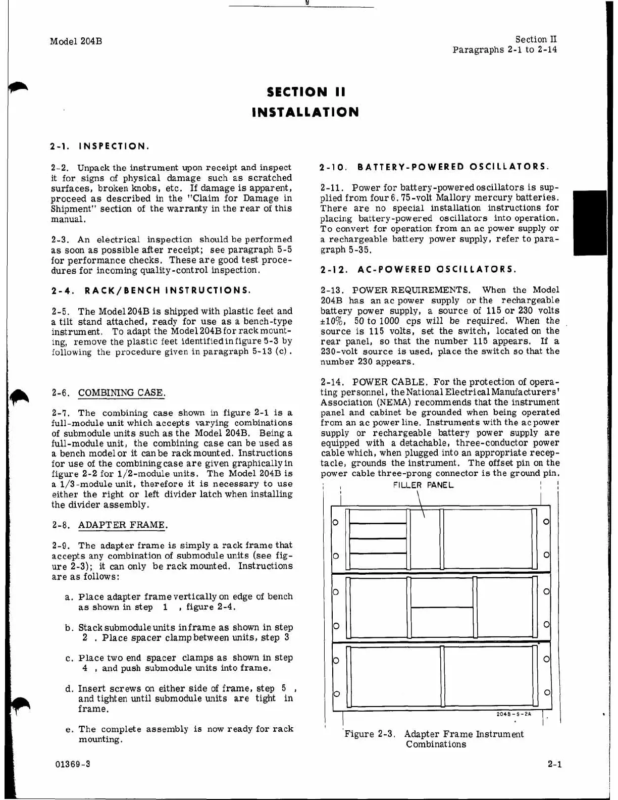
2-8. ADAPTER FRAME.
2-9. The adapter frame
is
simply
a
rack frame that
accepts any combination of submodule units (see fig-
ure 2-3);
it
can only be rack mounted. Instructions
are
as
follows:
a.
Place adapter frame vertically on edge of bench
as
shown in step
1
,
figure 2-4.
b. Stacksubmoduleunits in
frame
as
shown in step
2
,
Place spacer clamp between units, step 3
c. Place two end spacer clamps
as
shown in step
4
,
and push submodule units into frame.
d. Insert screws on either side of frame, step
5
,
and tighten until submodule units are tight in
frame.
e. The complete assembly
is
now ready for rack
mounting.
2-10.
BATTERY-POWERED OSCILLATORS.
2-11,
Power for battery-powered oscillators
is
sup-
plied from four 6.75-volt Mallory mercury batteries.
There are no special installation instructions for
placing battery -powered oscillators into operation.
To convert for operation from an ac power supply or
a
rechargeable battery power supply, refer to para-
graph 5-35.
2-12.
AC-POWERED OSCILLATORS.
2-13. POWER REQUIREMENTS. When the Model
204B has an ac power supply or the rechargeable
battery power supply,
a
source of 115
or
230 volts
+lo%,
50 to
1000
cps will be required. When the
source
is
115
volts, set the switch, located on the
rear panel,
so
that the number 115 appears.
If
a
230-volt source
is
used, place the switch
so
that the
number 230 appears.
2-14. POWER CABLE. For the protection of opera-
ting personnel, the National Electrical Manufacturers'
Association (NEMA) recommends
that
the instrument
panel and cabinet be grounded when being operated
from an ac power line. Instruments with the acpower
supply or rechargeable battery power supply are
equipped with
a
detachable, three-conductor power
cable which, when plugged into an appropriate recep-
tacle, grounds the instrument. The offset pin on the
power cable three-prong connector
is
the ground pin.
FILLER
PANEL
Figure 2-3. Adapter Frame Instrument
Combinations
01369-3
2-1