Section
111
Model
204B
Figure
3-1
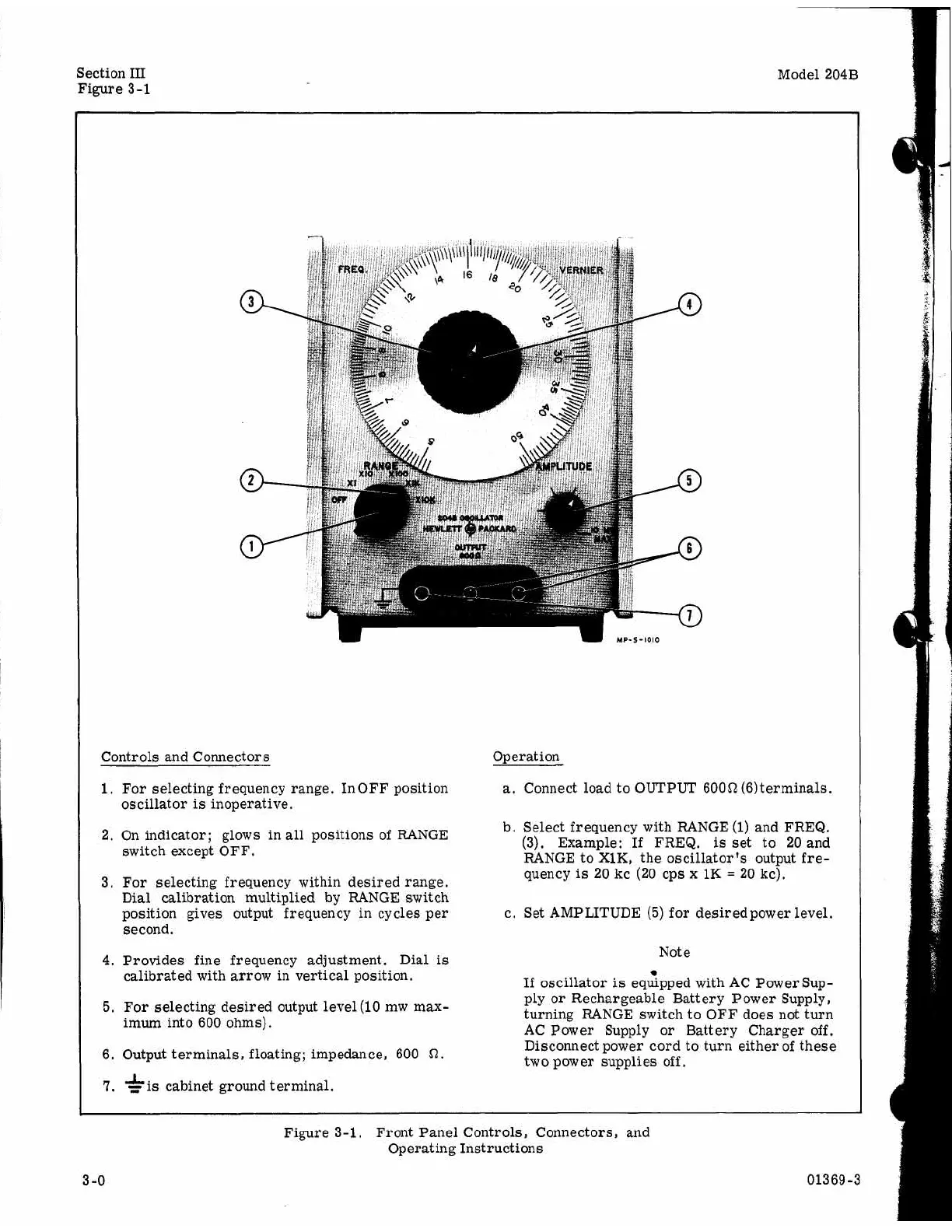
Controls and Connectors
1.
For selecting frequency range. In
OFF
position
oscillator
is
inoperative.
2.
On indicator; glows in
all
positions of RANGE
switch except OFF.
3.
For selecting frequency within desired range.
Dial calibration multiplied by RANGE switch
position gives output frequency in cycles per
second.
4.
Provides fine frequency adjustment. Dial
is
5.
For
selecting desired output level (10 mw max-
calibrated with arrow in vertical position.
imum into 600 ohms).
6. Output terminals, floating; impedance, 600
7.
cabinet ground terminal.
Operation
a.
Connect load to
OUTPUT
60052(6)
terminals.
b. Select frequency with RANGE
(1)
and FREQ.
(3). Example: If FREQ.
is
set
to
20
and
RANGE to XlK, the oscillator's output
fre-
quency
is
20
kc
(20
cps
x
1K
=
20
kc).
c. Set AMPLITUDE
(5)
for desired power level.
Not
e
If
oscillator
is
equipped with AC Paver Sup-
ply
or
Rechargeable Battery Power Supply,
turning RANGE switch to OFF does not turn
AC Power Supply
or
Battery Charger off.
Disconnect power cord to turn either
of
these
two power supplies off,
Figure 3-1. Front Panel Controls, Connectors, and
Operating Instructions
3
-0
01369-3