Section
V
Paragraphs 5-38 to 5-46
Model 204B
5-38.
BATTERY-PACK POWER SUPPLY.
5-39.
To
convert an AC-powered
or
rechargeable
battery-powered Model 204B for operation from
mercury batteries, obtain
a
standard Battery Pack,
@
Stock No. 204B-64B. Install Battery-Pack Power
Supply according to instructions included with kit
,
Refer to paragraph 3-26 for battery replacement
instructions.
5-40.
AC POWER SUPPLY.
5-41. To convert
a
battery-powered
or
rechargeable
battery-powered Model 204B for operation from AC
power, obtain AC Power Supply Kit, @Stock No,
204B-11A. (Refer to figures 5-8 and 5-12.) Install
AC-Operated Power Supply according to instructions
included with kit.
5-42.
RECHARGEABLE BATTERY POWER SUPPLY.
5-43. The Rechargeable Battery Power Supply can
replace the standard Battery Pack
or
the AC Power
Supply. This supply contains four 6.25 volt sealed
nickel-cadmium batteries which permit portable
operation and
a
charge circuit which operates from
a
115/230 volt (selected by switch on rear panel S101)
50
to
1000 cps power line, Power input to this power
supply
is
approximately 3 watts. To convert an AC
powered
or
a
battery-powered Model 204B for oper-
ation from
a
rechargeable battery power supply,
obtain Rechargeable Battery
Kit,
@
Stock No. 204B-
11C. Install Rechargeable Battery Power Supply
according to instructions included with kit.
5-44. After Rechargeable Battery Power Supply has
been installed, turn oscillator on and check maximum
output voltage level. If level
is
below 5.0
V
rms
open circuit
(2.
5
V
rms into 600 ohms), turn osci-
llator OFF and recharge batteries following the pro-
cedure
in
paragraph 3-16.
CAUTION
BE SURE TO PLACE 115/230 VOLT
LINE SWITCH (S101) IN PROPER
POSITION BEFORE CONNECTING
POWER CORD TO A POWER SOURCE.
(SEE PARAGRAPH 2-12.)
5-45. REPLACEMENT OF RECHARGEABLE
BATTERIES
.
5-46. When rechargeable batteries require replace-
ment, disconnect power cordandturn oscillator OFF.
The following procedure
is
recommended:
a.
Disconnect power cord and remove top, bottom
and side covers.
b. Remove six screws holding rear panel in place
.
c. Remove four screws holding battery charger
circuit board in place.
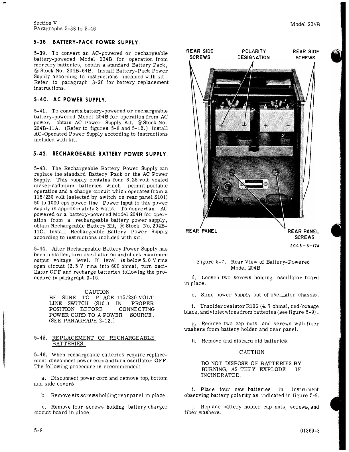
REAR SIDE
POLARITY REAR SIDE
SCREWS
DES
I
G
NATION SCREWS
RE
AR’PANEL
”
REAR PANEL
SCREWS
2048-6-17A
Figure 5-7. Rear View of Battery-Powered
Model 204B
d. Loosen two screws holding oscillator board
in place.
e. Slide power supply out
of
oscillator chassis.
f.
Unsolder resistor R106 (4.7 ohms), red/orange
black, andviolet wires from batteries (see figure 5-9)
.
g. Remove two cap nuts and screws with fiber
washers from battery holder and rear panel,
h. Remove and discard old batteries.
CAUTION
DO
NOT DISPOSE OF BATTERIES BY
BURNING, AS THEY EXPLODE IF
IN CINE RATED,
i.
Place four new batteries in instrument
observing battery polarity
as
indicated in figure
5-9.
j.
Replace battery holder cap nuts, screws, and
fiber washers.
5-8
0
13 69-
3