Model 204B Section
V
Paragraphs 5-36 to 5-37
TO POWER SUPPLY
(OPTION
02
ONLY)
TO POWER SUPPLY
(OPTION
02
ONLY)
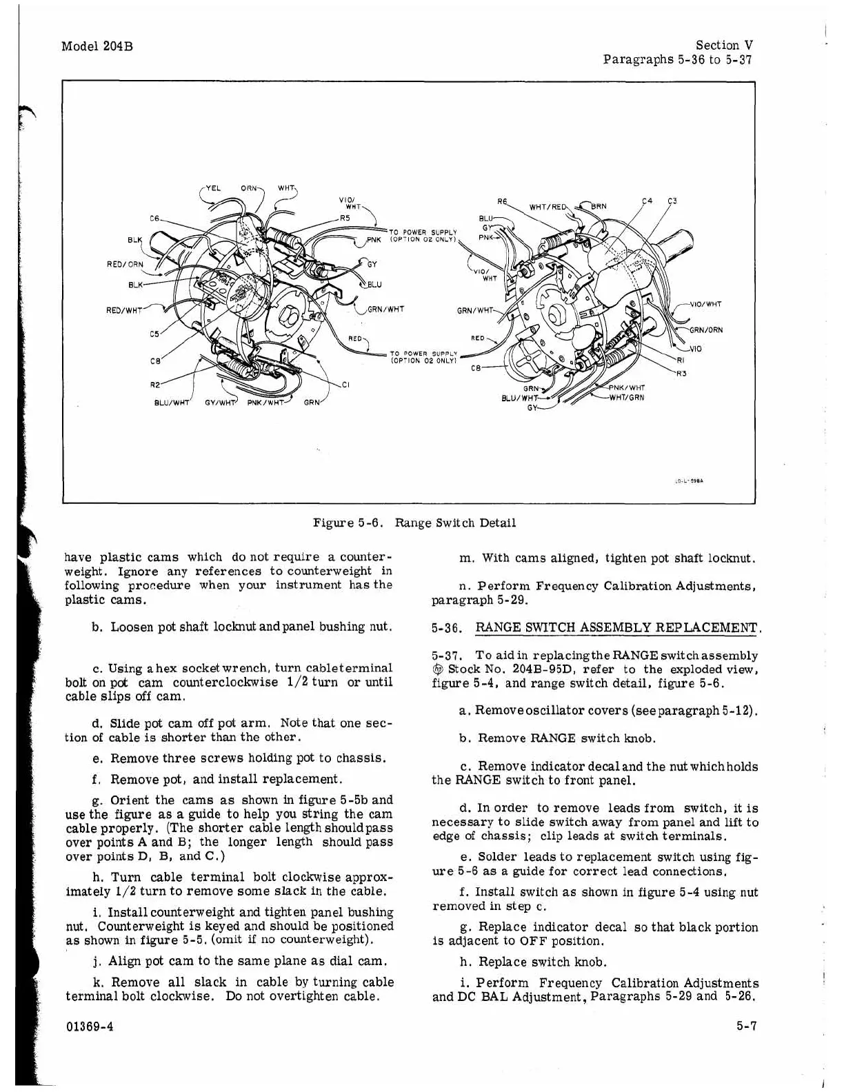
Figure 5-6. Range Switch Detail
have plastic cams which do not require
a
counter-
weight. Ignore any references to counterweight in
following procedure when your instrument has the
plastic cams.
b. Loosen pot shaft locknut and panel bushing nut,
c. Using
a
hex socket wrench, turn cableterminal
bolt on pot cam counterclockwise 1/2 turn
or
until
cable slips off cam.
d. Slide pot cam off pot arm. Note that one sec-
tion of cable
is
shorter than the other.
e. Remove three screws holding pot to chassis.
f.
Remove pot
,
and install replacement.
g.
Orient the cams
as
shown in figure 5-5b and
use the figure
as
a
guide to help you string the cam
cable properly. (The shorter cable length should pass
over points
A
and B; the longer length should pass
over points
D,
B, and C.)
h.
Turn cable terminal bolt clockwise approx-
imately 1/2 turn to remove some slack
in
the cable,
i.
Install counterweight and tighten panel bushing
nut. Counterweight
is
keyed and should be positioned
as shown in figure 5-5. (omit
if
no counterweight).
j.
Align pot cam to the same plane
as
dial cam.
k.
Remove
all
slack in cable by turning cable
terminal bolt clockwise. Do not overtighten cable.
01369-4
m. With cams aligned, tighten pot shaft locknut.
n. Perform Frequency Calibration Adjustments,
paragraph 5-29.
5-36. RANGE SWITCH ASSEMBLY REPLACEMENT.
5-37. To aidin replacingthe RANGE switchassembly
@
Stock No. 204B-95D, refer to the exploded view,
figure 5-4, and range switch detail, figure 5-6.
a.
Removeoscillator covers (seeparagraph 5-12).
b. Remove RANGE switch knob.
c. Remove indicator decal and the nut which holds
the RANGE switch to front panel.
d. In order to remove leads from switch, it
is
necessary to slide switch away from panel and
lift
to
edge of chassis; clip leads at switch terminals.
e. Solder leads to replacement switch using fig-
ure 5-6
as
a
guide for correct lead connections.
f.
Install switch
as
shown in figure 5-4 using nut
removed in step c.
g. Replace indicator decal
so
that black portion
is
adjacent to OFF position.
h. Replace switch knob.
i.
Perform Frequency Calibration Adjustments
and DC BAL Adjustment, Paragraphs
5-29
and 5-26.
5-7