Model 204B
Section
V
Paragraphs 5-25 to 5-30
i
Note
Do not exceed
11
milliamperes.
A
charge current exceeding
11
milli-
amperes will shorten battery life.
Replace top cover.
5-26. DC BAL ADJUSTMENT,
5-27. When the DC BAL control R15
(rear
panel)
is
properly adjusted there should be no dc voltage present
at the oscillator output.
If
dc voltage
is
present, pro-
ceed
as
follows:
a.
Connect
a
DC voltmeter to oscillator output.
(With the optional Rechargeable Battery Power Supply,
connect DC voltmeter between floating ground and
the junction of L1 and C102.)
b. Set AMPLITUDE to MAX.
c.
Adjust DC BAL on
rear
of instrument for
a
zero
volt reading. If necessary, change the value of R18
for proper range of R15.
If
DC BAL will not adjust to
.zero volts, check power supply for proper voltages.
5-28. DISTORTION ADJUSTMENT,
a.
Connect
a
600-ohm loadacross the oscillator
output terminals.
b. Using an AC voltmeter, measure the gain con-
trol voltage between circuit ground and arm of poten-
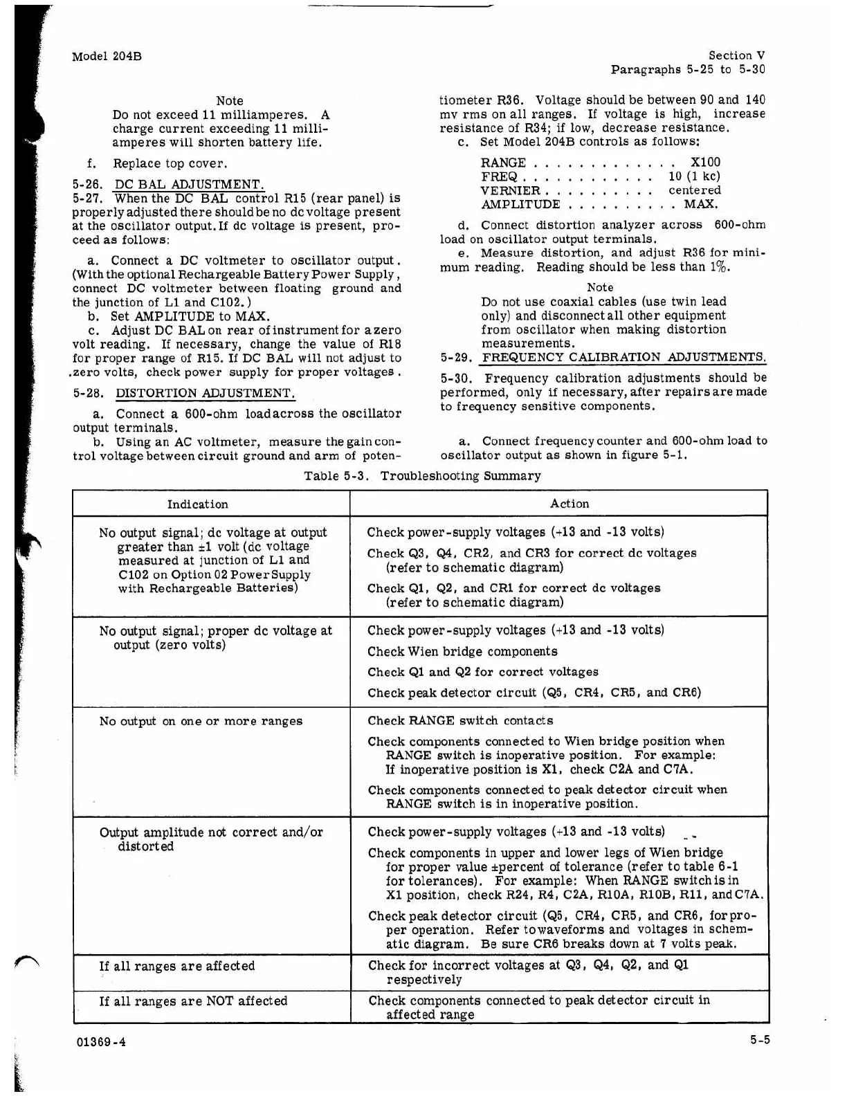
Table 5-3. Troubleshooting Summary
Indication
No output signal; dc voltage
at
output
greater than
k1
volt (dc voltage
measured at junction of L1 and
C102 on Option 02 Power Supply
with Rechargeable Batteries)
No output on one or more ranges
tiometer R36. Voltage should be between 90 and 140
mv rms on all ranges.
If
voltage
is
high, increase
resistance of R34;
if
low, decrease resistance.
c.
Set Model 204B controls
as
follows:
RANGE
.............
XI00
FREQ..
..........
lO(1kc)
VERNIER.
.........
centered
AMPLITUDE.
.........
MAX.
d. Connect distortion analyzer across 600-ohm
e.
Measure distortion, and adjust R36 for mini-
load on oscillator output terminals.
mum reading. Reading should be
less
than
1%.
Note
Do not use coaxial cables (use twin lead
only) and disconnect all other equipment
from oscillator when making distortion
measurements.
5-30. Frequency calibration adjustments should be
performed, only
if
necessary, after repairs
are
made
to frequency sensitive components.
5-29. FREQUENCY CALIBRATION ADJUSTMENTS.
a.
Connect frequency counter and 600-ohm load to
oscillator output
as
shown in figure 5-1.
No output signal; proper dc voltage
at
output (zero volts)
Output amplitude not correct and/or
distorted
If
all
ranges are affected
If
all
ranges
are
NOT affected
Action
Check power-supply voltages (+13 and -13 volts)
Check Q3,
Q4,
CR2, and CR3 for correct dc voltages
Check Q1, Q2, and CR1 for correct dc voltages
Check power-supply voltages (+13 and -13 volts)
Check Wien bridge components
Check Q1 and Q2 for correct voltages
Check peak detector circuit (Q5, CR4, CR5, and CR6)
Check RANGE switch contacts
Check components connected to Wien bridge position when
(refer
to schematic diagram)
(refer to schematic diagram)
RANGE switch
is
inoperative position. For example:
If
inoperative position
is
X1, check C2A and C7A.
RANGE switch
is
in inoperative position.
Check components connected to peak detector circuit when
Check power-supply voltages (+13 and -13 volts)
Check components in upper and lower legs of Wien bridge
I
for proper value *percent of tolerance
(refer
to table 6-1
for tolerances). For example: When RANGE switch
is
in
X1 position, check R24, R4, C2A, RlOA, RlOB, R11, andC7A
Check peak detector circuit (Q5, CR4, CR5, and CR6, forpro-
per operation. Refer towaveforms and voltages in schem-
atic diagram. Be sure CR6 breaks down at
7
volts peak.
respectively
Check for incorrect voltages
at
Q3,
Q4,
Q2, and Q1
~~ ~~
Check components connected to peak detector circuit
in
affected range
5-5
01369-4