Model 204B Section
V
Figure 5-8
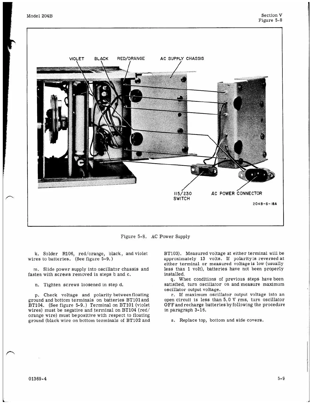
VIOLET BLACK RED/ORANGE
AC
SUPPLY CHASSIS
\
115/230
AC
POWER
CONNECTOR
SWITCH
204B-S-18A
Figure 5-8.
AC
Power Supply
k. Solder R106, red/orange, black, and violet
wires to batteries. (See figure 5-9.)
m. Slide power supply into oscillator chassis and
fasten with screws removed in steps b and c.
n.
Tighten screws loosened in step d.
p. Check voltage and polarity between floating
ground and bottom terminals
on
batteries BT101 and
BT104. (See figure 5-9.
)
Terminal
on
BT101 (violet
wires) must be negative and terminal
on
BT104 (red/
orange wire) must bepositive with respect to floating
ground (black wire
on
bottom terminals of BT102 and
BT103). Measured voltage at either terminal
will
be
approximately 13 volts. If polarity
is
reversed at
either terminal
or
measured voltage
is
low (usually
less than
1
volt), batteries have not been properly
installed.
g.
When conditions of previous steps have been
satisfied, turn oscillator
on
and measure maximum
oscillator output voltage.
r.
If
maximum oscillator output voltage into
an
open circuit
is
less than 5.0
V
rms, turn oscillator
OFF and recharge batteries by following the procedure
in paragraph 3-16.
s.
Replace top, bottom and side covers.
01369-4
5-9
 Loading...


