Model
204B
Section
V
Paragraphs
5-10
to
5-15
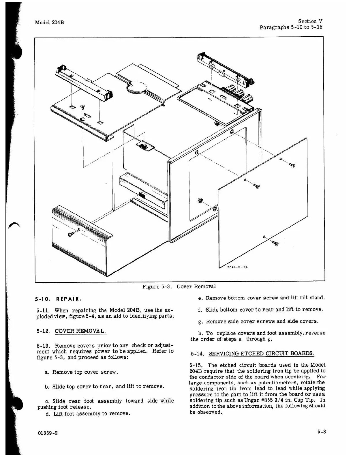
Figure
5-3.
Cover Removal
5-10.
REPAIR.
5-11.
When repairing the Model
204B,
use the ex-
ploded
view,
figure 5-4,
as
an aid to identifying parts.
5-12.
COVER REMOVAL.
5-13.
Remove covers prior to any check or adjust-
ment which requires power to be applied. Refer to
figure
5-3,
and proceed
as
follows:
a.
Remove top cover screw.
b. Slide top cover to rear, and
lift
to remove.
c. Slide rear foot assembly toward side while
d. Lift foot assembly to remove.
pushing foot release.
01369-2
e. Remove bottom cover screw and
lift
tilt
stand.
f.
Slide bottom cover to rear and lift to remove.
g. Remove side cover screws and side covers.
h. To replace covers and foot assembly, reverse
the order of steps
a
through g.
5-14.
SERVICING ETCHED CIRCUIT BOARDS.
5-15.
The etched circuit boards used in the Model
204B
require that the soldering iron tip be applied to
the conductor side of the board when servicing. For
large components, such
as
potentiometers, rotate the
soldering iron tip from lead to lead while applying
pressure to the part to
lift
it
from the board or use
a
soldering tip such as
Ungar
#855 3/4
in. Cup Tip. In
addition to the above information, the following should
be observed.
5-3