311
To do… Use the command…
Remarks
Display the ARP detection
statistics
display arp detection statistics [ interface
interface-type interface-number ] [ | { begin |
exclude | include } regular-expression ]
Available in any view
Clear the ARP detection
statistics
reset arp detection statistics [ interface
interface-type interface-number ]
Available in user view
ARP detection configuration example I
Network requirements
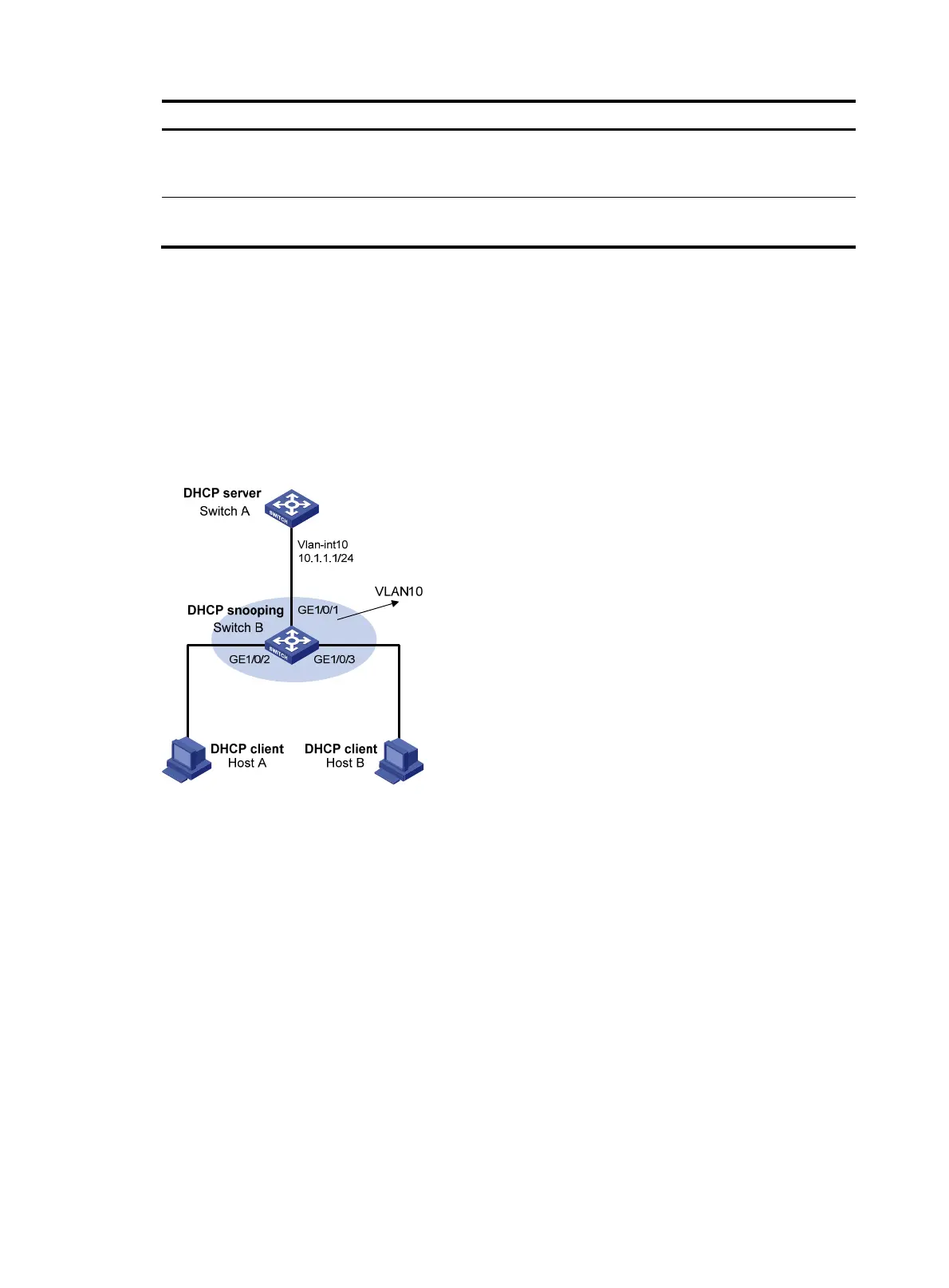
As shown in Figure 111, configure Switch A as a DHCP server and enable DHCP snooping on Switch B.
Configure Host A as a DHCP client. Configure Host B whose IP address is 10.1.1.6 and MAC address is
0001-0203-0607. Enable ARP detection for VLAN 10 to allow only packets from valid clients or hosts to
pass.
Figure 106 Network diagram for ARP detection configuration
Configuration procedure
1. Add all the ports on Switch B to VLAN 10, and configure the IP address of VLAN-interface 10 on
Switch A. (Omitted)
2. Configure Switch A as a DHCP server
# Configure DHCP address pool 0.
<SwitchA> system-view
[SwitchA] dhcp enable
[SwitchA] dhcp server ip-pool 0
[SwitchA-dhcp-pool-0] network 10.1.1.0 mask 255.255.255.0
3. Configure Host A as DHCP client, and Host B as user respectively. (Omitted)
4. Configure Switch B
# Enable DHCP snooping.
<SwitchB> system-view
[SwitchB] dhcp-snooping

 Loading...


