Single-ended TDR Measurements
Establishing the Reference Plane and Normalizing
7-10
1 Press the SETUP Time base key located below the display.
2 Change the
Scale
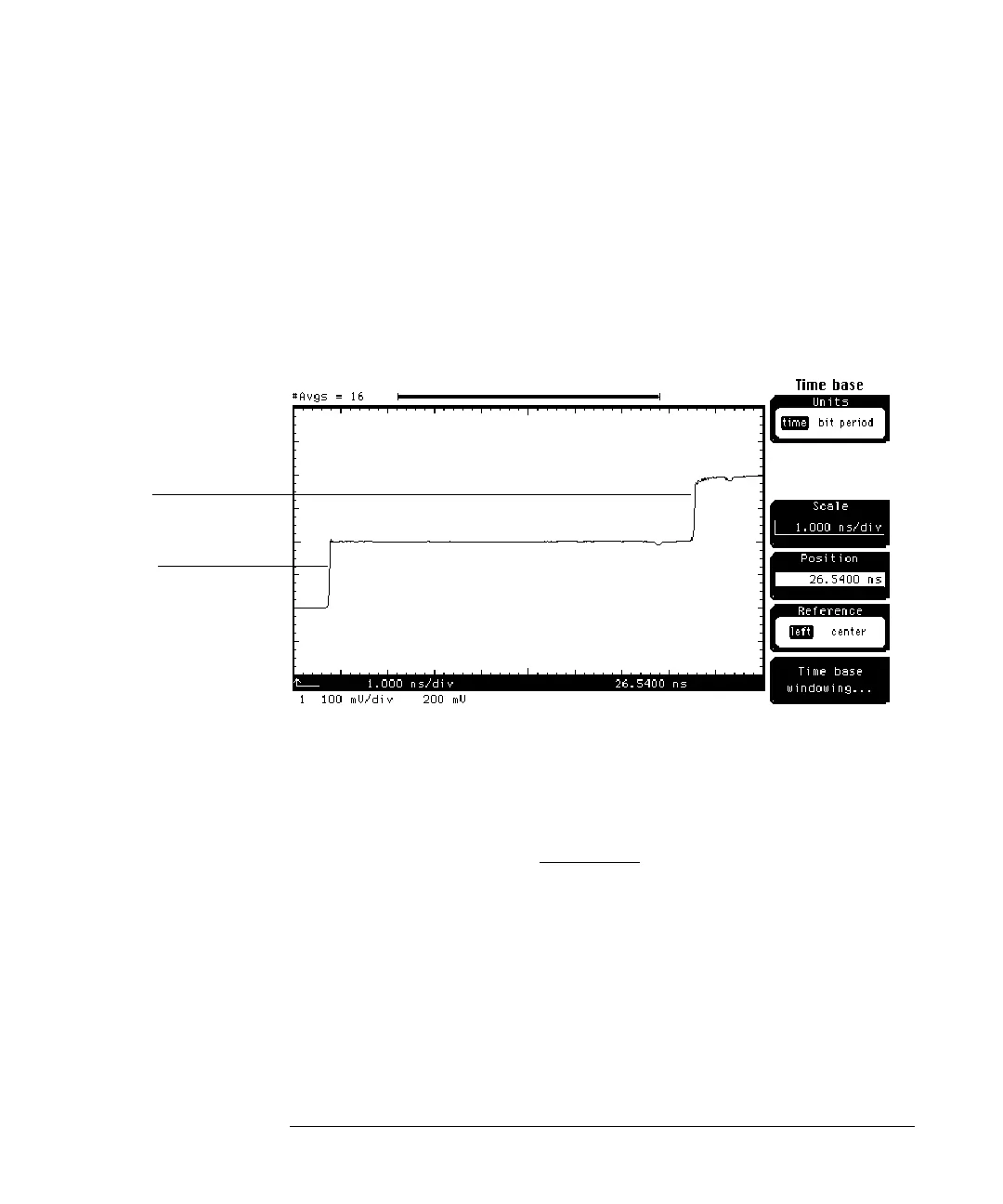
until you see two positive going edges on screen
(Figure 7-3).
The left-most edge is the incident step and starts at 0 mV and goes to 200 mV.
The right-most edge is the reflected step that has traveled from the TDR step
generator to the end of the cable and back to the TDR sampler. This step starts
at 200 mV and goes to 400 mV.
Figure 7-3
1 Change the
Scale
and
Position
to approximately center the incident step
in the middle of the display and to move the reflected step off screen.
2 Press the
blue key followed by the 7 key to turn the automated risetime
measurement on and select
channel 1.
Incident Step
Reflected Step