Single-ended TDR Measurements
Establishing the Reference Plane and Normalizing
7-12
1 Change the
Position
until the reflected edge is displayed at the
approximate center of the display.
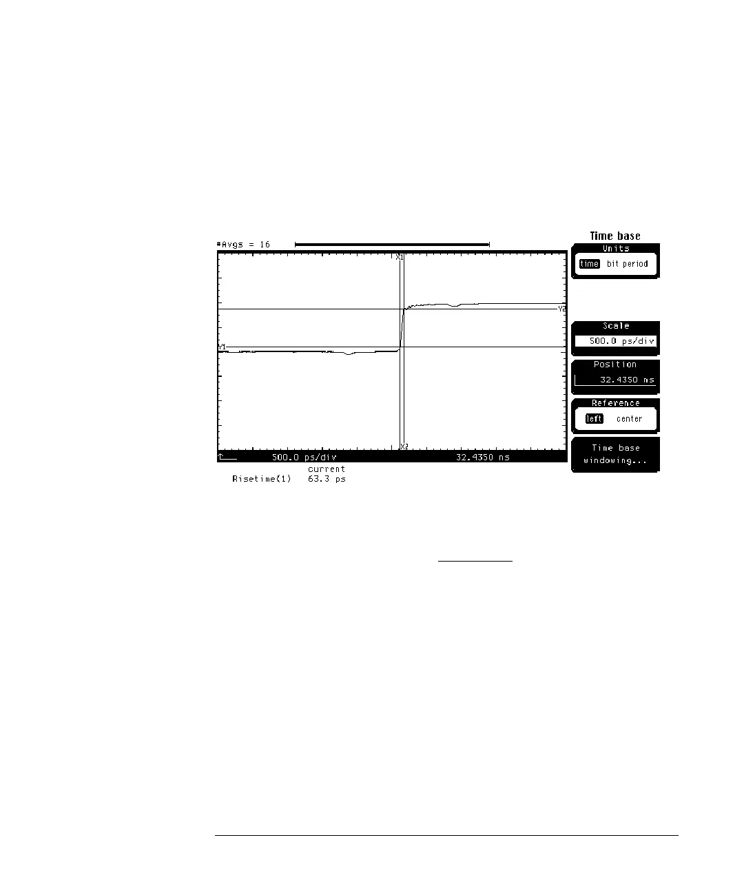
You should see a display similar to the one shown in Figure 7-5, however, the
risetime will depend on the quality of cable being used.
Figure 7-5
Note that the risetime of the reflected step is greater than the 40 ps of the
incident step. This difference is due to the losses in the cable and connectors.
1 Press the blue key followed by the 8 key to turn on the automated
Falltime measurement and select
channel 1.
2 Press the
Enter
softkey.
3 Connect an SMA short to the end of the cable.
4 Press the
Clear display key. Whenever an external connection is changed,
Clear display should be pressed to reset averaging.
You should see a display similar to the one in Figure 7-6.