Differential TDR Measurements
Measuring Differential and Common Mode Impedance
8-8
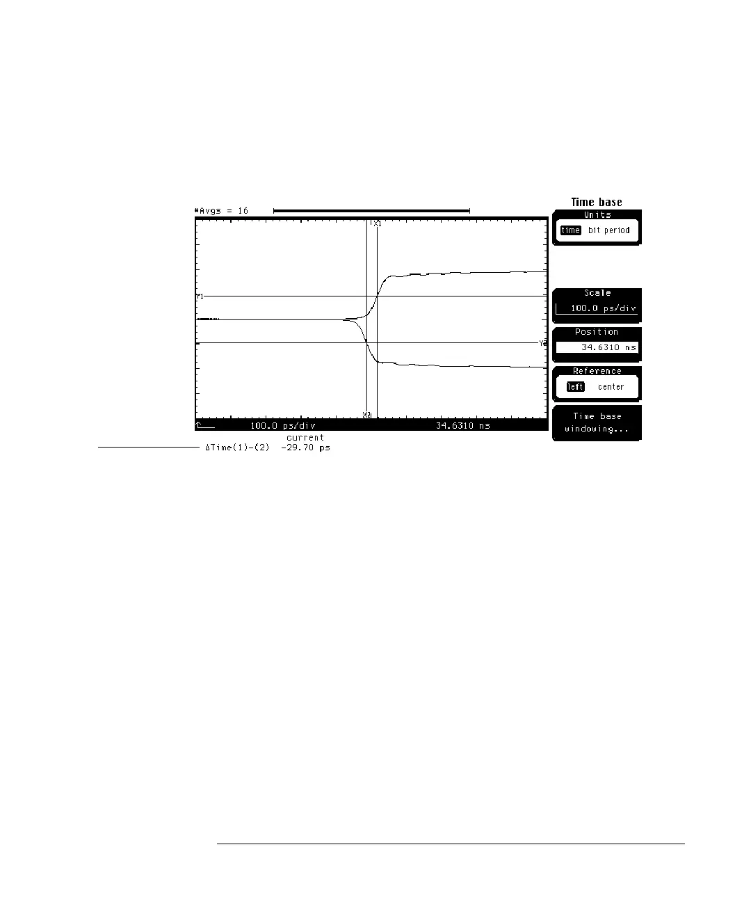
4 Change the
Position
until the reflected edge is approximately centered
in the display (Figure 8-3).
Figure 8-3
A ∆time (skew) value of 7 ps (one fifth the TDR step risetime of 35 ps) or less
is small enough that the skew will not introduce errors into TDR measurements.
However, for the purposes of demonstration, the following process shows how
to deskew the cables.
1 Press the SETUP Channel key for the channel whose reflected step is the
right-most step on the display.
2 Press the
Calibrate . . .
softkey.
3 Change the
Skew
until the ∆Time is ½ its initial value.
4 Change the
TDR Skew
until the remaining ∆Time is approximately 0. You
will need to move the control slowly as it takes a short amount of time
for the waveform to settle (Figure 8-4).
Measured Skew