Differential TDR Measurements
Measuring Differential and Common Mode Impedance
8-13
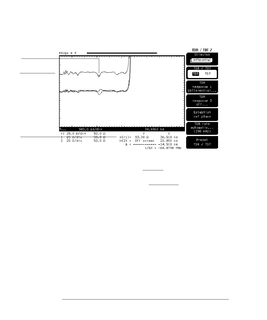
Figure 8-8
1 Press the SETUP Marker key.
2 Press the
Mode
softkey and select TDR/TDT.
3 Press the
Enter
softkey.
4 Press the
+ Source
softkey and select response 1.
5 Press the
Enter
softkey.
6 Change the
+ Position
until the + marker is on screen.
As the + marker moves along the waveform, the differential impedance at the
current + marker is shown at the bottom of the disp lay. If yo u move the + marker
to the portion of the waveform representing the cable response, the impedance
is the sum of the two cable impedances (approximately 100 ohms depending
on the quality of the cable). The negative bump where the + marker is located
in Figure 8-8 is the parasitic capacitance due to the leg of the switch connected
to the trace.
Response 1
Waveform
Differential
Impedance
Switch connection