Differential TDR Measurements
Making Differential TDT Measurements
8-21
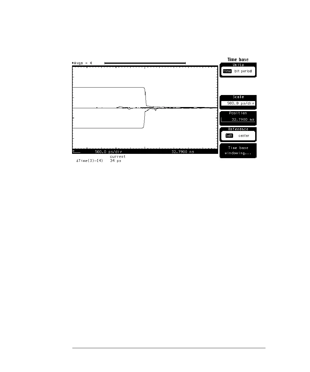
Figure 8-14
1 Press the electrical plug-in module’s SETUP Channel key whose waveform
is closest to the right side of the display. (For the example shown in
Figure 8-14, channel 4 is chosen.)
2 Press the
Calibrate . . .
softkey.
3 Change the
Skew
until the ∆Time is reduced to approximately 0 ps.
4 Press the
Done
softkey.
This completes the deskewing process for the TDT channels.
TDT Response Analysis
Analyzing TDT responses can help determine problems in differential lines. The
following procedure will show how to use TDT find a problem on the demo
board.
1 Remove the female-to-female adapters from both cable pairs.
2 Connect the channel 1 cable to the differential line closest to the single
transmission line on the demo board.
3 Connect the channel 3 cable to the other end of the differential line
closest to the single transmission line on the demo board.
4 Connect the channel 2 cable to the differential line closest to the edge
of the demo board.
 Loading...


