TDR Fundamentals
Step Reflection Testing
9-15
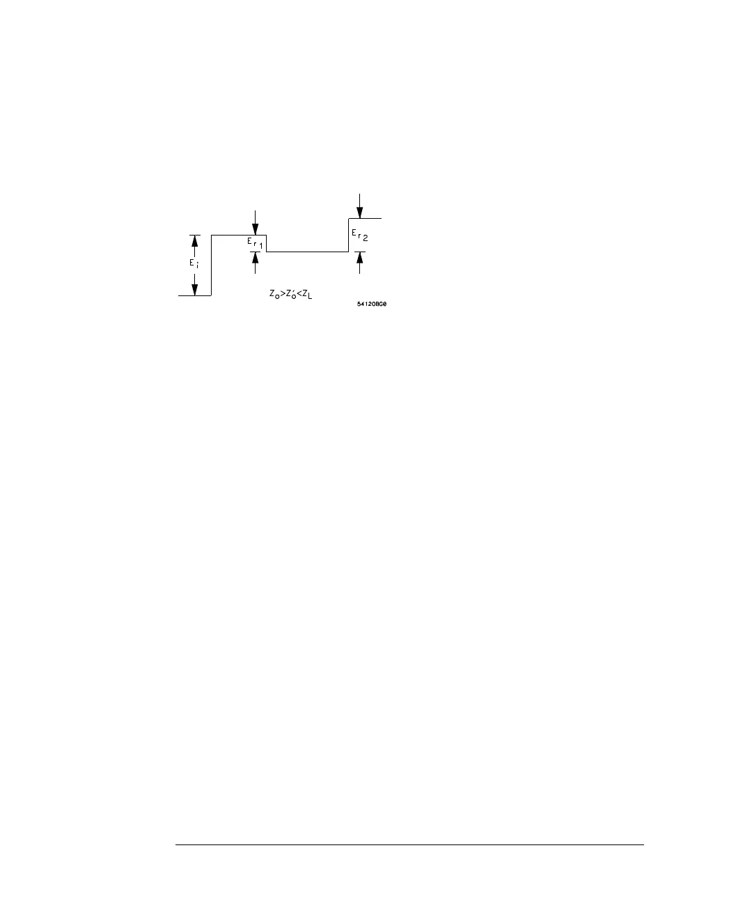
The oscilloscope's display for this situation would be similar to the diagram in
Figure 9-13 (drawn for the case where Z
L
> Z
o
> Z’
o
):
Figure 9-13
It is seen that the two mismatches produce reflections that can be analyzed
separately. The mismatch at the junction of the two transmission lines
generates a reflected wave, E
r1
, where
Similarly, the mismatch at the load also creates a reflection due to its reflection
coefficient
Two things must be considered before the apparent reflection from Z
L
, as shown
on the oscilloscope, is used to determine ρ
2
. First, the voltage step incident on
Z
L
is (1 + ρ
1
) E
i
, not merely E
i
: Second, the reflection from the load is
but this is not equal to E
r2
since a re-reflection occurs at the mismatched
junction of the two transmission lines. The wave that returns to the monitoring
point is
Since ρ
1
′ = -ρ
1
, E
r2
may be re-written as:
E
r
1
ρ
1
E
i
Z
o
′
Z
o
–
Z
o
′
Z
o
+
-------------------
E
i
==
ρ
2
Z
L
Z
o
′
–
Z
L
Z
o
′
+
-------------------=
ρ
2
1
ρ
1
+
()
E
i
[]
E
rL
=
E
r
2
1
ρ
1
′
+
()
E
rL
1
ρ
1
′
+
()ρ
2
1
ρ
1
+
()
E
i
[]
==
E
r
2
ρ
2
1
ρ
1
2
–
()[]
E
i
=