Improving Time Domain Network Measurements
Removing Measurement Errors
10-19
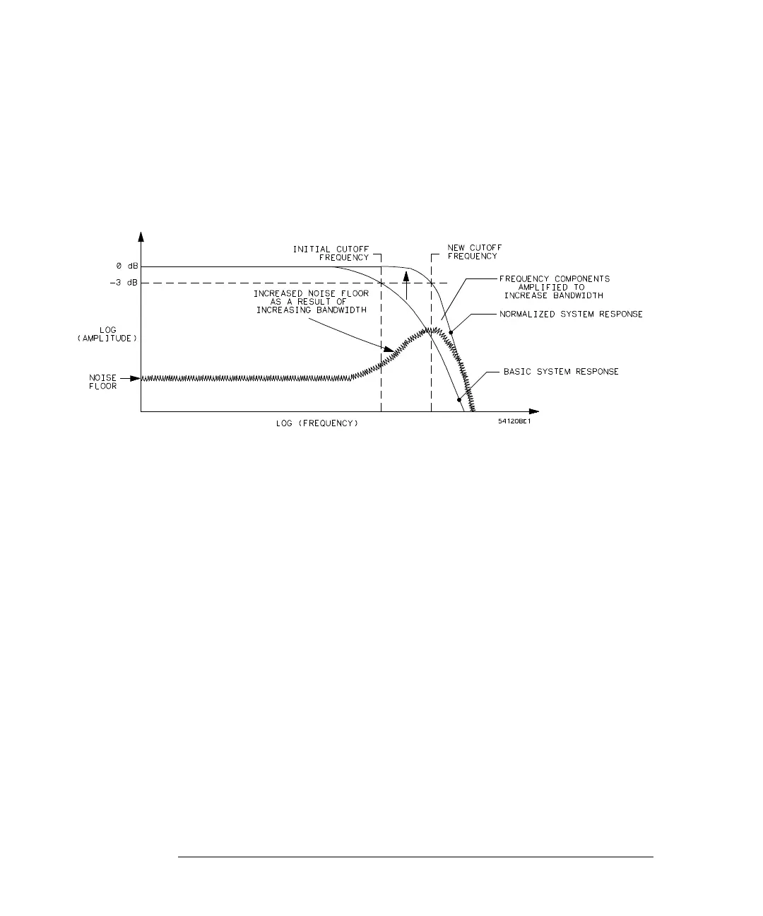
To increase the bandwidth, the response beyond the initial -3 dB frequency
needs to be amplified. While this is a valid step, it is important to realize that
the system noise at these frequencies and at nearby higher frequencies is also
amplified (see Figure 10-15).
Figure 10-15
Normalized system frequency response (system bandwidth increased)
The limit to which the risetime of real systems may be extended is determined
by the noise floor. In real systems, there is a point beyond which the amplitude
of the frequency response data is below the noise floor. Any further increase
in bandwidth only adds noise.
Because waveform averaging reduces the initial level of the noise floor,
WAVEFORM AVERAGING SHOULD BE USED WHEN NORMALIZING.
An equation can be used to describe the filtering process. The test system
frequency response, S(f), can be thought of as the ideal frequency response
defined by the sum of cosines window, W(f) multiplied by an error frequency
response, E(f) (see equation 4). Further, the measured response of the DUT,
M(f), can be thought of as the DUT frequency response, D(f), multiplied by the
test system frequency response, S(f). Filtering is accomplished by multiplying
the measured frequency response of the DUT by the filter, F(f). N(f) is the
normalized (filtered) frequency response of the DUT. Equation 5 describes the
filtering process using the above definitions.
(4)
Sf() Wf()Ef()=
 Loading...


