Transmission Line Theory Applied to Digital Systems
Transmission Line Design
11-11
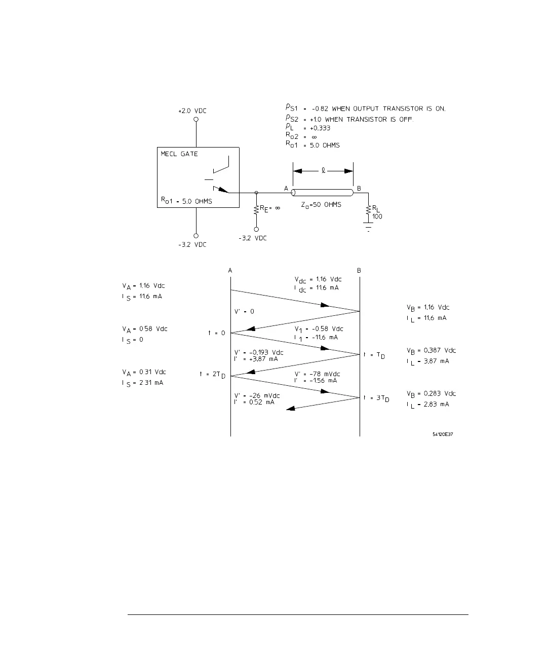
Figure 11-5
Lattice Diagram for Negative-Going Voltage Transition
To determine the voltage V
1
at t = 0, the following equation results from the
application of Ohm's Law to the circuit:
(7)
For the example shown, let R
E
= ∞, then:
V
1
I
dc
V
A
3.2
V
1
++
R
E
---------------------------------+
Z
o
=