165
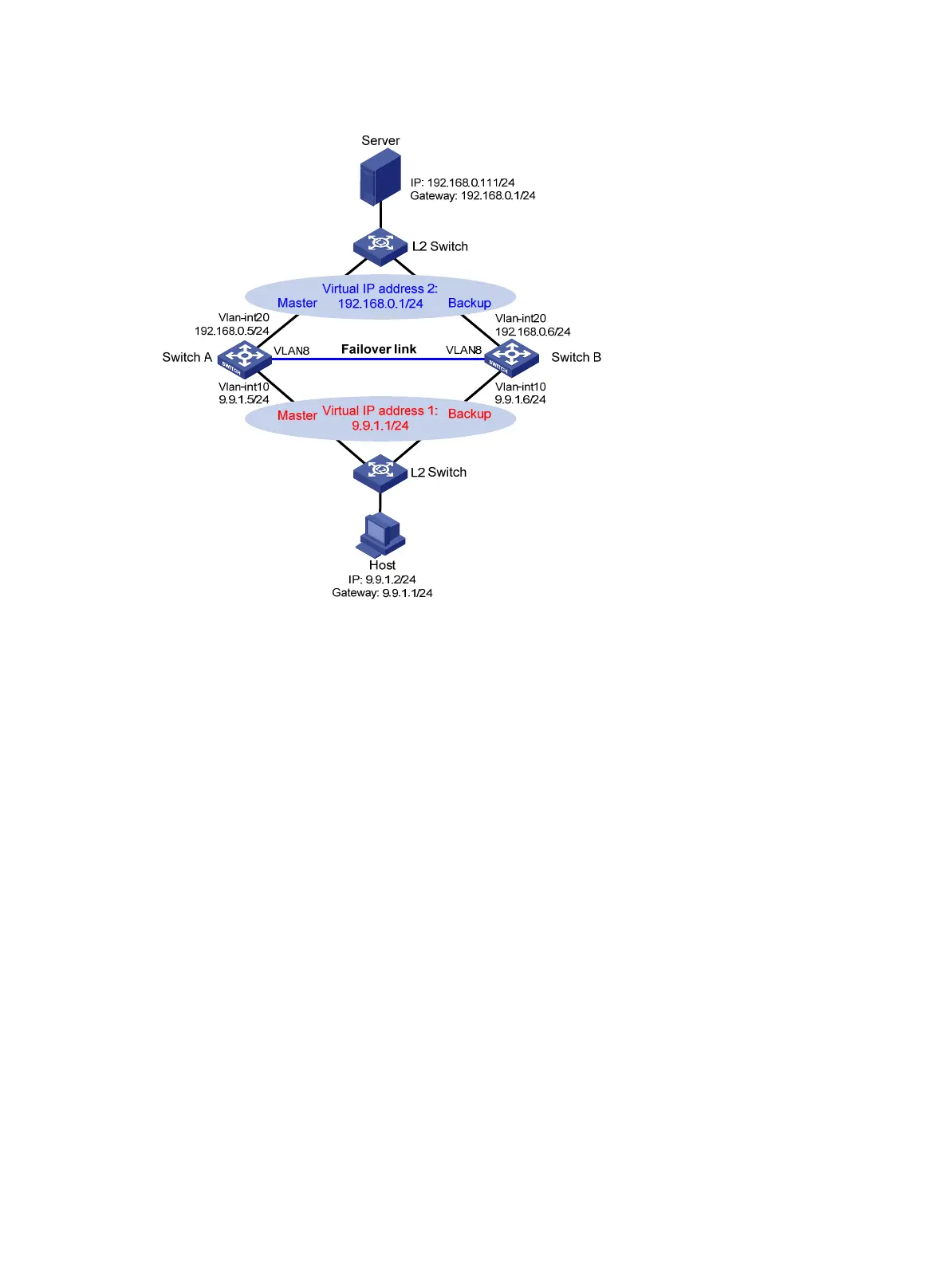
Figure 56 Network diagram
Configure IP addresses for the host, server, and switches as shown in Figure 56 and make sure that they
can reach to each other.
Make sure that Host can access the authentication server through Switch A and Switch B.
Configure VRRP group 1 and VRRP group 2 to implement backup for downstream and upstream links,
respectively. For more information about VRRP, see High Availability Configuration Guide.
For information about stateful failover configuration, see High Availability Configuration Guide.
Configuring the portal server (IMC PLAT 5.0)
This example assumes that the portal server runs on IMC PLAT 5.0(E0101) and IMC UAM 5.0(E0101).
# Configure the portal server.
Log in to IMC and select the Service tab. Then, select User Access Manager > Portal Service
Management > Server from the navigation tree to enter the portal server configuration page, as shown
in Figure 57.
C
onfigure the portal server parameters as needed. This example uses the default settings.

 Loading...


