Model
552BA
Conlro
l~
,
C
OIIIII
,:1.:
1015
,
Indi
cators
.
............................
.
••••••••••••••
••
•••
• ••••
•••••
•
••••
••
•••
•
••••
••••••••••••
••
• •
••••••••••••
••••••••••••
••
••
••••••••••••
••••••••••••
••
Ii
, ..................
::
..
:
..
.
••
••••••••••••
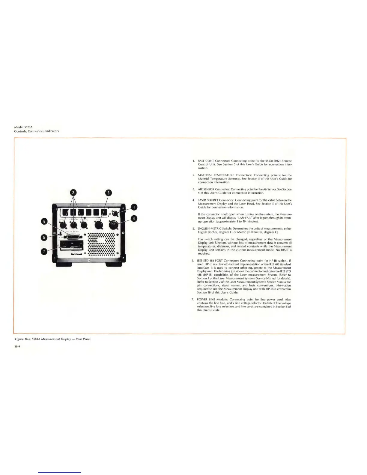
Figure 16·2.
550BA
Me
;l5uremenr Display - Rear Panel
16
-4
1. RMT CONT Connector: Connecling point for the
05
5
08-600
21 Remole
Conlrol Unit.
See
Section 5
of
this User
's
Guide for
(;o
nnection infor-
mation.
2.
MATERIAL
TEMPERATURE
ConnCC:lor5
: Connecting pOinl(5) for the
Material
Temperature
Sensor
(s
).
See
Se(;tion 5 of this
User's
Guide for
connection information.
3.
AIR
SENSOR
Connector: Connecting point for thc AirSen
so
r.
See
Section
5 of this User's Guide for co nnection information.
4.
LASER
SOURCE
Connec
tor
: Connecting point for the cable bel ween the
Measurement Display and Ihe laser Head.
Sec
Section 5 of
Ihi
s
Use
r
's
Guide for connection information.
If thiS connec
tor
is
left open when turning
on
the
sys
tem, Ihe Measure-
ment Display unit
wiU
di
splay
''lASr
FAil
" after it goes through
its
warm-
up
ope
ra
tion (approximately 3 to
10
minutes
).
S.
ENGLIS
H-METRIC Switch; Determines the units of mea
su
rement
s,
either
Engli
sh
(inc
hes
, degrees F)
or
Metric
(millimetres, degrees C) .
The switch selling c
an
be changed, regardless of the Measurement
Display unit function, without l
oss
of
mea
surement data. It converts all
temperatures, distances, and related constants while the Measurement
Display unit remains in the current
mea
surement mode.
No
RESET
is
required .
6.
IEEE
srD
488
PORT
Connector: Connecting point for HP-IB cable{s
),
if
used
. Hp·
IB
is a Hewlett-Packard Implementation of the I
EEE
488Slandard
Interf
ace.
It
is
used
to connect other equipment to Ihe Measurement
Display unit.
Th
e lettering just above the connector indic
ates
the I
EEE
STD
488
(
HP
-
IB
)
c~pabi
lit
ies
of the
la
ser
mea
su
rement
System.
(Refer to
Section 3
of
the
Laser
Measurement
System's
Ser
vi
ce
Manual for details).
Refer to Section 2 of the laser Measurement
Sys
tem's Service Manual for
pin connections,
signal names, and
10Bi
c convention
s.
Information
required to u
se
the Measurement
Di
splay unit with
HP
-
IB
is covered in
Section
18
of
this User's Guide.
7.
POWER
LINE
Module
; Connecting point for line power cord. Al
so
contains the line fuse, and a line voltage
se
lector. Details
of
line vo
ltag
e
se
lection, line fu se selection,
if
nd line cords
if
re contained in Section 5
of
th
is
User
's
GUide.