I/O modules
Two I/O modules provide the interface between the drive enclosure and the host controllers. See
Figure 7 (page 27). They route data to and from the disk drives using Loop A and Loop B, the
dual-loop configuration. For redundancy, only dual-controller, dual-loop operation is supported.
Each controller is connected to both I/O modules in the drive enclosure.
Figure 7 I/O module
1. Status indicators (Upper port, Power, and Lower port)
2. Upper port
3. Lower port
The I/O modules are functionally identical, but are not interchangeable. Module A can only be
installed at the right end of the enclosure, and module B can only be installed at the left end of the
enclosure. See Figure 6 (page 26).
Each I/O module has two ports that can both transmit and receive data for bidirectional operation.
Activating a port requires connecting a FC cable to the port. The port function depends upon the
loop. See Figure 8 (page 27).
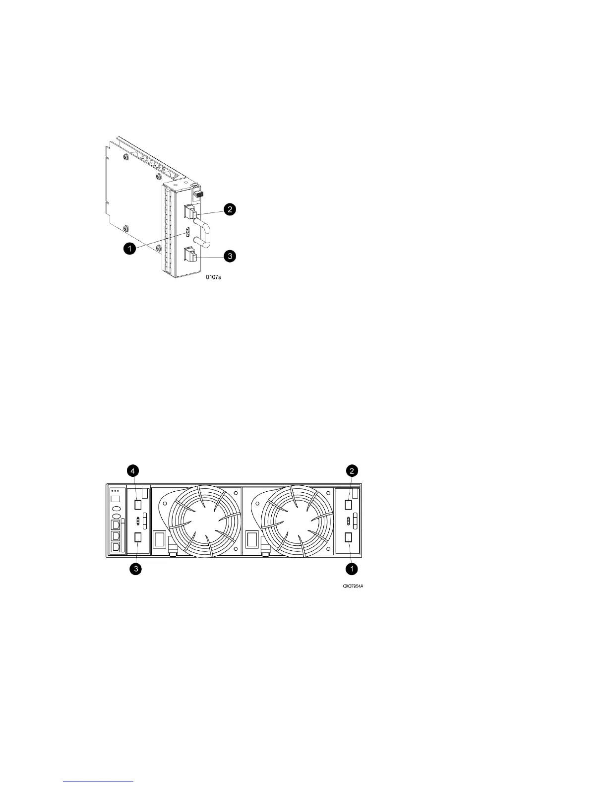
Figure 8 Input and output ports
2. Loop A upper port1. Loop A lower port
4. Loop B upper port3. Loop B lower port
I/O module status indicators
There are three status indicators on the I/O module. See Figure 7 (page 27). The status indicator
states for an operational I/O module are shown in Table 2 (page 28). Table 3 (page 28) shows
the status indicator states for a non-operational I/O module.
Fibre Channel drive enclosures 27