Adj
u
5
t
r
ie
n
t
s
Model
8Y04A
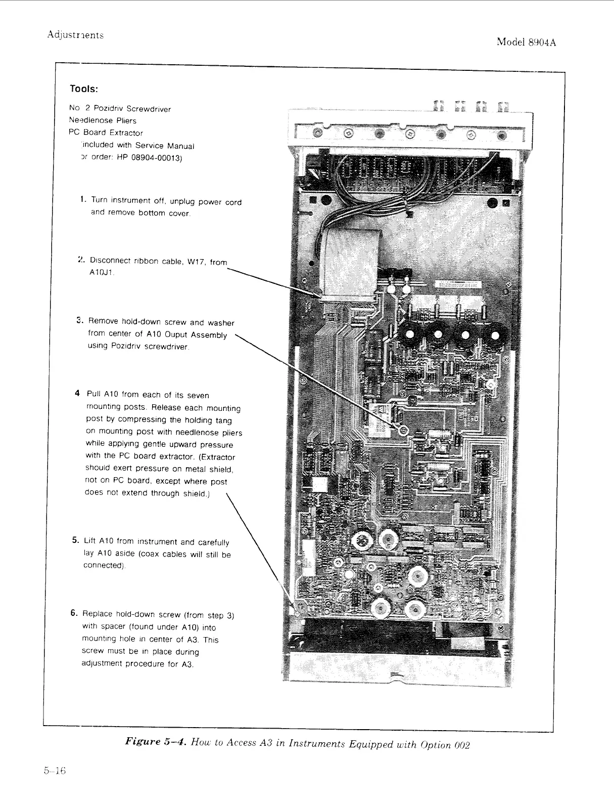
Tools:
No
2
Pozidriv Screwdriver
Nerdlenose Pliers
PC Board Extractor
included with Service Manual
3r
order HP 08904-00013)
I.
Turn instrument off, unplug power cord
and remove bottom cover
2.
Disconnect ribbon cable,
W17,
from
\
AlOJ1
3.
Remove hold-down screw and washer
from center
of
A10 Ouput Assembly
using Pozidriv screwdriver
\
4
Pull
A10
from each of its seven
rriounting posts Release each mounting
post by compressing the holding tang
on mounting post with needlenose pliers
while applying gentle upward pressure
with the PC board extractor (Extractor
should exert pressure on metal shield,
riot on PC board, except where post
does not extend through shield
)
lay A10 aside (coax cables will still be
5.
Lift A10 fromi instrument and carefully
connected)
6.
Replace hold-down screw (from step 3)
with spacer (found under ,410) into
mounting hole in center of A3 This
screw must be in place during
adjustment procedure for A3
-I
I
-1
-___
I-_
Figure
5-4.
Hou
to
Access
A3
in
Instruments
Equipped
uith
Option
(102
Artisan Technology Group - Quality Instrumentation ... Guaranteed | (888) 88-SOURCE | www.artisantg.com


 To Next Page