HP
8904A
Option
005
3A-3
@
RESET
SYNC CLOCK
INPUT OUTPUT INPUT OUTPUT
@@@@
@
RESET
-
INPUT
RESET
SYNC CLOCK
INPUT OUTPUT INPUT OUTPUT
@OOO
POWER
S
PLl
TT
E
RS
The
@
RESET OUTPUT signal is input here to provide the phase reset
signal that establishes a new phase starting point for the output
signals.
If
the instrument
is
configured as the Master controller, its
own
@
RESET OUTPUT signal must be routed back to this connector
for the instrument to function properly.
50
OHM
Detailed Operating
lnsfrucfions
Cable Connections
HP
8904A-
SLAVE
Y2
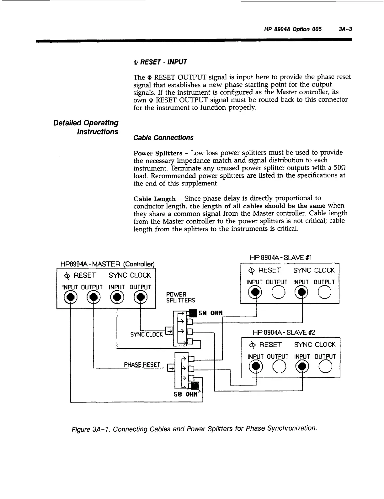
Power Splitters
-
Low loss power splitters must be used to provide
the necessary impedance match and signal distribution to each
instrument. Terminate any unused power splitter outputs with
a
50R
load. Recommended power splitters are listed in the specifications at
the end of this supplement.
Cable Length
-
Since phase delay
is
directly proportional to
conductor length,
the length of all cables should be the same
when
they share a common signal from the Master controller. Cable length
from the Master controller to the power splitters is not critical; cable
length from the splitters to the instruments
is
critical.
PHASERESET
r;
INPUT OUTWT INPUT OUTPUT
QOOO
E5
I
Figure
3A-1.
Connecting Cables and Power Splitters
for
Phase Synchronization.
Artisan Technology Group - Quality Instrumentation ... Guaranteed | (888) 88-SOURCE | www.artisantg.com